Page 1 of 1
Pseudo Differentiator 1. For the first order high-pass filter in Fig. 4, derive the time-domain equation for the output
Posted: Fri Jul 01, 2022 6:08 am
by answerhappygod
- Pseudo Differentiator 1 For The First Order High Pass Filter In Fig 4 Derive The Time Domain Equation For The Output 1 (48.37 KiB) Viewed 77 times
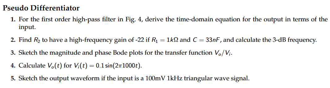
Pseudo Differentiator 1. For the first order high-pass filter in Fig. 4, derive the time-domain equation for the output in terms of the input. 2. Find R₂ to have a high-frequency gain of -22 if R₁ = 1kN and C = 33nF, and calculate the 3-dB frequency. 3. Sketch the magnitude and phase Bode plots for the transfer function V₁/V₁. 4. Calculate Vo(t) for Vi(t) = 0.1 sin(2T1000t). 5. Sketch the output waveform if the input is a 100mV 1kHz triangular wave signal.
R₁ C The output voltage in Fig. 4 can be found as + V V₂ = R₂ +5V s+ 4 N1 N2 Figure 4: Pseudo differentiator circuit R₂ S R₁ 5 -5V 1 R₁C V₂ V; (4)