Page 1 of 1
PINA301 12. A flow control valve is installed in a pipeline as shown in Figure 1. A 1450 rpm pump with impellor diameter
Posted: Fri Jul 01, 2022 5:59 am
by answerhappygod
- Pina301 12 A Flow Control Valve Is Installed In A Pipeline As Shown In Figure 1 A 1450 Rpm Pump With Impellor Diameter 1 (55.92 KiB) Viewed 29 times
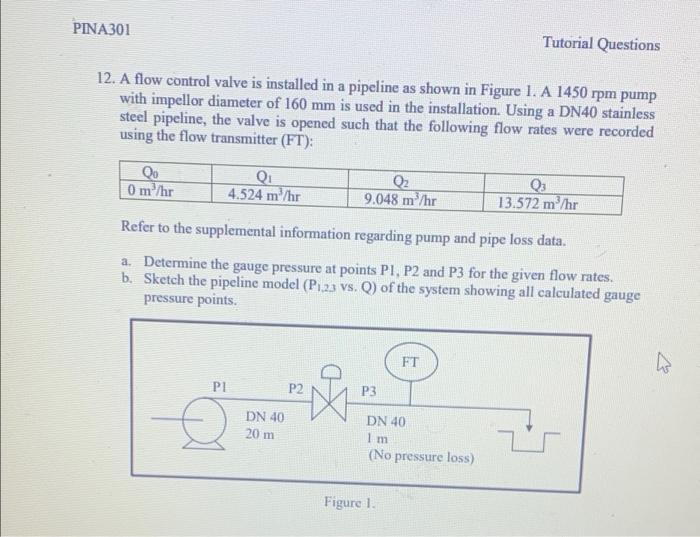
PINA301 12. A flow control valve is installed in a pipeline as shown in Figure 1. A 1450 rpm pump with impellor diameter of 160 mm is used in the installation. Using a DN40 stainless steel pipeline, the valve is opened such that the following flow rates were recorded using the flow transmitter (FT): Qo 0 m³/hr Q₁ 4.524 m³/hr PI DN 40 20 m Q₂ 9.048 m³/hr Refer to the supplemental information regarding pump and pipe loss data. a. Determine the gauge pressure at points P1, P2 and P3 for the given flow rates. b. Sketch the pipeline model (P1,23 vs. Q) of the system showing all calculated gauge pressure points. P2 P3 Tutorial
Questions FT DN 40 1 m (No pressure loss) Figure 1. Q₁ 13.572 m³/hr