Page 1 of 1
V E. -10 -15 0.005 Fig. 1 Half wave rectifier circuit 0.01 2:1 0.01 Fig. 2 Full wave rectifier circuit Input signal 0.01
Posted: Fri Jul 01, 2022 5:37 am
by answerhappygod
- V E 10 15 0 005 Fig 1 Half Wave Rectifier Circuit 0 01 2 1 0 01 Fig 2 Full Wave Rectifier Circuit Input Signal 0 01 1 (47.5 KiB) Viewed 38 times
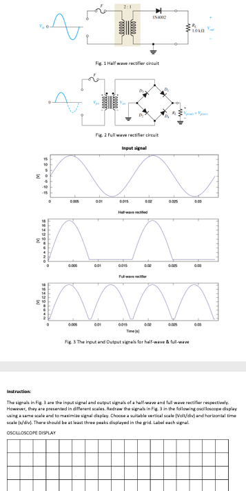
V E. -10 -15 0.005 Fig. 1 Half wave rectifier circuit 0.01 2:1 0.01 Fig. 2 Full wave rectifier circuit Input signal 0.01 0.015 Dh 0.015 Hallwave rectified 0.015 IN4002 0.02 0.00 0.02 •1010 Fig. 3 The input and Output signals for half-wave & full-wave 0.03 Instruction: The signals in Fig. 3 are the input signal and output signals of a half-wave and full wave rectifier respectively. However, they are presented in different scales. Redraw the signals in Fig. 3 in the following oscilloscope display using a same scale and to maximize signal display. Choose a suitable vertical scale (Volt/div) and horizontal time scale (s/div). There should be at least three peaks displayed in the grid. Label each signal. OSCILLOSCOPE DISPLAY