Page 1 of 1
5.1 Arithmetic circuit (a) Derive a sketch of the circuit. The diagram should have about 5 to 10 blocks (which can be ad
Posted: Fri Jul 01, 2022 5:37 am
by answerhappygod
- 5 1 Arithmetic Circuit A Derive A Sketch Of The Circuit The Diagram Should Have About 5 To 10 Blocks Which Can Be Ad 1 (36.85 KiB) Viewed 40 times
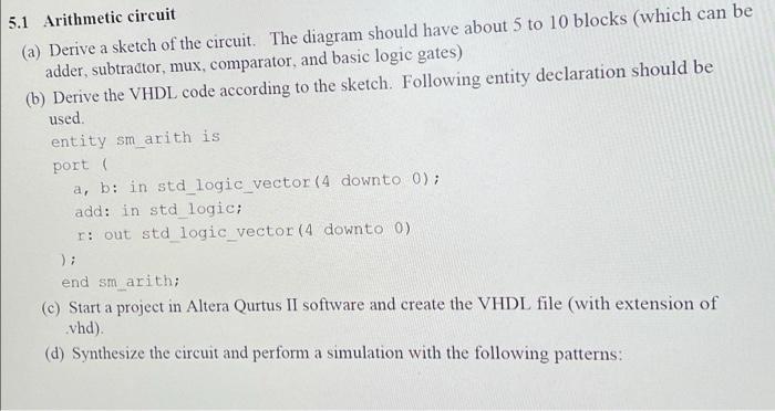
5.1 Arithmetic circuit (a) Derive a sketch of the circuit. The diagram should have about 5 to 10 blocks (which can be adder, subtractor, mux, comparator, and basic logic gates) (b) Derive the VHDL code according to the sketch. Following entity declaration should be used. entity sm arith is port ( a, b: in std_logic_vector (4 downto 0); add: in std_logic; r: out std_logic_vector (4 downto 0) end sm_arith; (c) Start a project in Altera Qurtus II software and create the VHDL file (with extension of .vhd). (d) Synthesize the circuit and perform a simulation with the following patterns: