Page 1 of 1
In Fig. Q1, bus 1 is the slack bus with V1 = 1.02/0° pu. Assuming the initial voltage at the load bus to be 1.0/0° pu an
Posted: Sat Mar 19, 2022 6:13 pm
by answerhappygod
- In Fig Q1 Bus 1 Is The Slack Bus With V1 1 02 0 Pu Assuming The Initial Voltage At The Load Bus To Be 1 0 0 Pu An 1 (124.27 KiB) Viewed 45 times
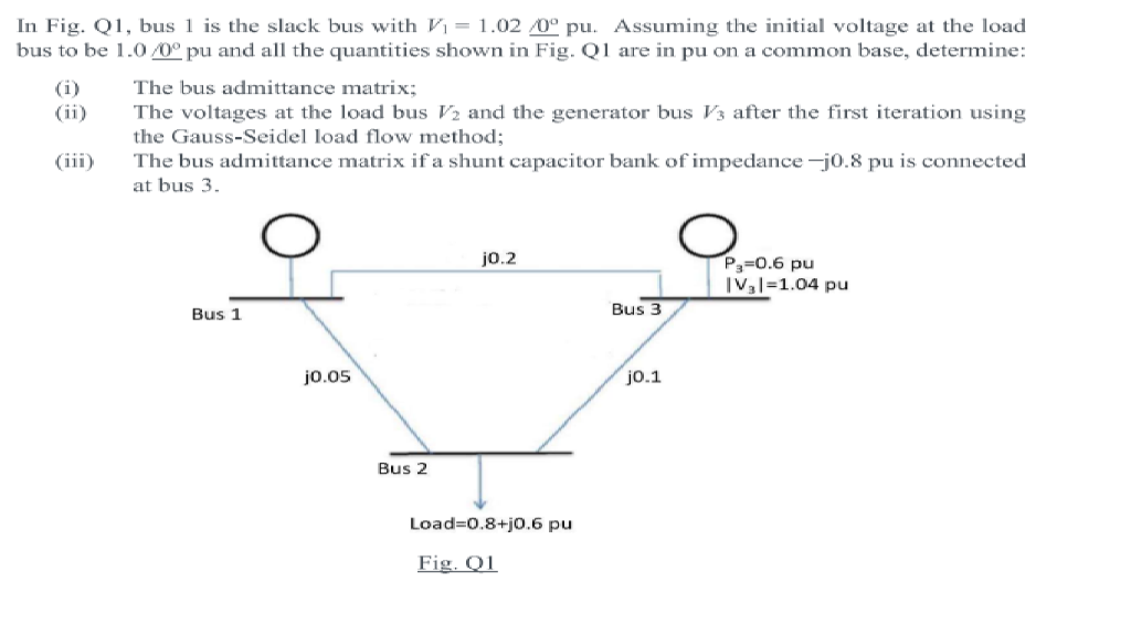
In Fig. Q1, bus 1 is the slack bus with V1 = 1.02/0° pu. Assuming the initial voltage at the load bus to be 1.0/0° pu and all the quantities shown in Fig. Q1 are in pu on a common base, determine: (i) The bus admittance matrix; The voltages at the load bus V2 and the generator bus V3 after the first iteration using the Gauss-Seidel load flow method; (iii) The bus admittance matrix if a shunt capacitor bank of impedance-j0.8 pu is connected at bus 3. O j0.2 Pg=0.6 pu IV,I=1.04 pu Bus 1 Bus 3 j0.05 j0.1 Bus 2 Load=0.8+j0.6 pu Fig. 01