Page 1 of 1
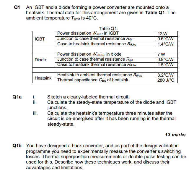
Q1 An IGBT and a diode forming a power converter are mounted onto a heatsink. Thermal data for this arrangement are give
Posted: Sat Mar 19, 2022 6:09 pm
by answerhappygod
- Q1 An Igbt And A Diode Forming A Power Converter Are Mounted Onto A Heatsink Thermal Data For This Arrangement Are Give 1 (124.47 KiB) Viewed 82 times
Q1 An IGBT and a diode forming a power converter are mounted onto a heatsink. Thermal data for this arrangement are given in Table Q1. The ambient temperature Tambis 40°C. Table Q1. Power dissipation Wicer in IGBT Junction to case thermal resistance Rejc Case to heatsink thermal resistance Rechs IGBT 12 W 0.6°C/W 1.4°C/W Diode Power dissipation WDIODE in diode Junction to case thermal resistance Rajc Case to heatsink thermal resistance Rechs 7W 0.9°C/W 1.5°C Heatsink to ambient thermal resistance Rensa Heatsink Thermal capacitance Cons of heatsink 3.2°C/W 280 °C Q1a i. Sketch a clearly-labeled thermal circuit. ii. Calculate the steady-state temperature of the diode and IGBT junctions. iii. Calculate the heatsink's temperature three minutes after the circuit is de-energised after it has been running in the thermal steady-state. 13 marks Q1b You have designed a buck converter, and as part of the design validation programme you need to experimentally measure the converter's switching losses. Thermal superposition measurements or double-pulse testing can be used for this. Describe how these techniques work, and discuss their advantages and limitations.