Page 1 of 1
2) 2) connector shaft bi 12 R NODOO w (1) Ti(t) Ideal Gearbox V(1) wit) i(t) Ovoco ri Jw motor T16 ground bearing Im wz(
Posted: Fri Mar 04, 2022 10:10 am
by answerhappygod
- 2 2 Connector Shaft Bi 12 R Nodoo W 1 Ti T Ideal Gearbox V 1 Wit I T Ovoco Ri Jw Motor T16 Ground Bearing Im Wz 1 (69.25 KiB) Viewed 46 times
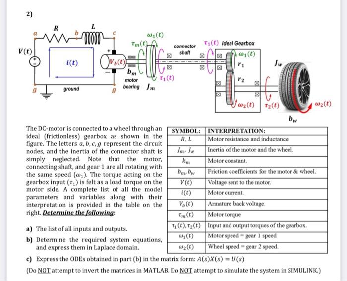
2) 2) connector shaft bi 12 R NODOO w (1) Ti(t) Ideal Gearbox V(1) wit) i(t) Ovoco ri Jw motor T16 ground bearing Im wz(t) 12(1) bw The DC-motor is connected to a wheel through an SYMBOL: INTERPRETATION: ideal (frictionless) gearbox as shown in the R.L Motor resistance and inductance figure. The letters a, b,c,g represent the circuit nodes, and the inertia of the connector shaft is Imi Iw Inertia of the motor and the wheel simply neglected. Note that the motor, km Motor constant connecting shaft, and gear 1 are all rotating with bm.bw Friction coefficients for the motor & wheel. the same speed (w). The torque acting on the gearbox input (T) is felt as a load torque on the V(1) Voltage sent to the motor. motor side. A complete list of all the model (1) Motor current parameters and variables along with their interpretation is provided in the table on the V.(t) Armature back voltage right. Determine the following: Motor torque a) The list of all inputs and outputs. 77().T2() Input and output torques of the gearbox (6) Motor speed - gear I speed b) Determine the required system equations, and express them in Laplace domain. w2(1) Wheel speed gear 2 speed. c) Express the ODEs obtained in part(b) in the matrix form: A(s)X(s) = V(s) (Do NOT attempt to invert the matrices in MATLAB. DO NOT attempt to simulate the system in SIMULINK.) (1)