Page 1 of 1
STRESSES IN GEAR TEETH (ANALYSIS USING MDESIGN) 1. OBJECTIVE: 1.1 To study MDESIGN mechanical design software. 1.2 To co
Posted: Fri Mar 04, 2022 10:06 am
by answerhappygod
- Stresses In Gear Teeth Analysis Using Mdesign 1 Objective 1 1 To Study Mdesign Mechanical Design Software 1 2 To Co 1 (62.43 KiB) Viewed 47 times
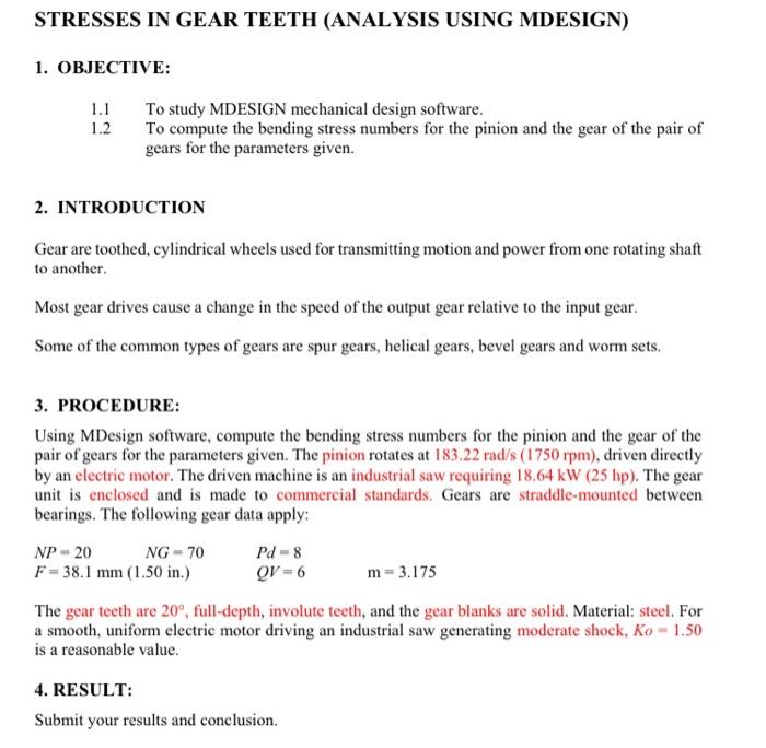
STRESSES IN GEAR TEETH (ANALYSIS USING MDESIGN) 1. OBJECTIVE: 1.1 To study MDESIGN mechanical design software. 1.2 To compute the bending stress numbers for the pinion and the gear of the pair of gears for the parameters given. 2. INTRODUCTION Gear are toothed, cylindrical wheels used for transmitting motion and power from one rotating shaft to another Most gear drives cause a change in the speed of the output gear relative to the input gear. Some of the common types of gears are spur gears, helical gears, bevel gears and worm sets. 3. PROCEDURE: Using MDesign software, compute the bending stress numbers for the pinion and the gear of the pair of gears for the parameters given. The pinion rotates at 183.22 rad/s (1750 rpm), driven directly by an electric motor. The driven machine is an industrial saw requiring 18.64 kW (25 hp). The gear unit is enclosed and is made to commercial standards. Gears are straddle-mounted between bearings. The following gear data apply: NP - 20 NG - 70 Pd - 8 F = 38.1 mm (1.50 in.) QV - 6 m-3.175 The gear teeth are 20%, full-depth, involute teeth, and the gear blanks are solid. Material: steel. For a smooth, uniform electric motor driving an industrial saw generating moderate shock, Ko - 1.50 is a reasonable value. 4. RESULT: Submit your results and conclusion.