Page 1 of 1
11. Determine the displacements and rotation at B for the frame in Figure P4.11. Take E=210 kN/mm², 1 = 20 x 10-m' and A
Posted: Fri Mar 04, 2022 9:56 am
by answerhappygod
- 11 Determine The Displacements And Rotation At B For The Frame In Figure P4 11 Take E 210 Kn Mm 1 20 X 10 M And A 1 (29.75 KiB) Viewed 45 times
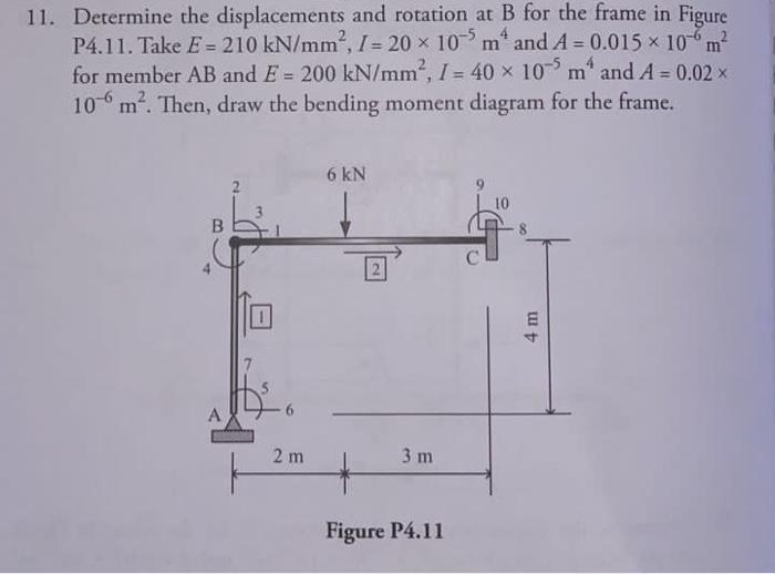
11. Determine the displacements and rotation at B for the frame in Figure P4.11. Take E=210 kN/mm², 1 = 20 x 10-m' and A = 0.015 x 10 m² for member AB and E = 200 kN/mm², I = 40 x 10 m' and A = 0.02 10m². Then, draw the bending moment diagram for the frame. 6 kN B 1 4 m 2 m 3 m + Figure P4.11