Page 1 of 1
A series RL circuit is shown in the figure below. The voltage across the inductor is treated as the output and the appli
Posted: Sat Feb 19, 2022 3:28 pm
by answerhappygod
- A Series Rl Circuit Is Shown In The Figure Below The Voltage Across The Inductor Is Treated As The Output And The Appli 1 (46.35 KiB) Viewed 72 times
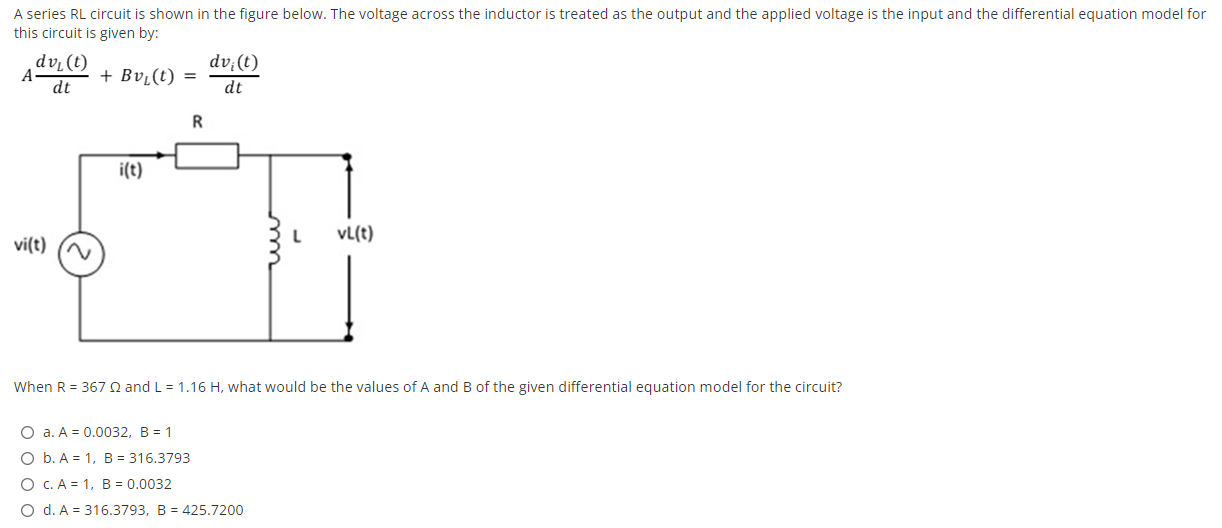
A series RL circuit is shown in the figure below. The voltage across the inductor is treated as the output and the applied voltage is the input and the differential equation model for this circuit is given by: dv.(t) dvic) A + Bv.(t) = dt dt R i(t) ། vl(t) vi(t) (N L When R = 367 and L = 1.16 H, what would be the values of A and B of the given differential equation model for the circuit? O a. A = 0.0032, B = 1 O b. A = 1, B = 316.3793 O C. A = 1, B = 0.0032 O d. A = 316.3793, B = 425.7200