Page 1 of 1
Q6. (a) The single phase half-bridge inverter in Fig. 26(a), has a load with resistance of R = 25 12, The DC input volta
Posted: Fri Jan 21, 2022 8:42 am
by answerhappygod
- Q6 A The Single Phase Half Bridge Inverter In Fig 26 A Has A Load With Resistance Of R 25 12 The Dc Input Volta 1 (47.9 KiB) Viewed 55 times
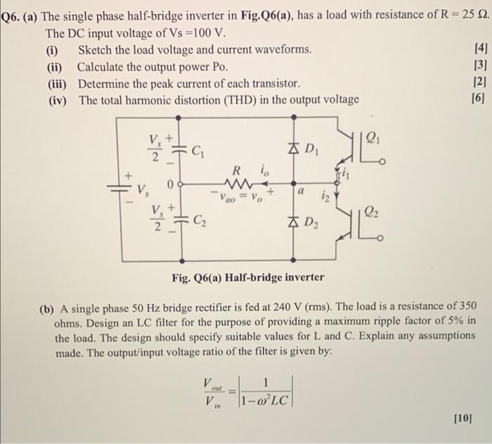
Q6. (a) The single phase half-bridge inverter in Fig. 26(a), has a load with resistance of R = 25 12, The DC input voltage of Vs =100 V. (i) Sketch the load voltage and current waveforms. [4] (ii) Calculate the output power Po. [3] (iii) Determine the peak current of each transistor [2] (iv) The total harmonic distortion (THD) in the output voltage [6] + AD - Ri TH a V. 12 V 04 V, + C2 Q2 KD2 Fig. Q6(a) Half-bridge inverter (b) A single phase 50 Hz bridge rectifier is fed at 240 V (rms). The load is a resistance of 350 ohms, Design an LC filter for the purpose of providing a maximum ripple factor of 5% in the load. The design should specify suitable values for L and C. Explain any assumptions made. The output/input voltage ratio of the filter is given by: V V wat omedel ou! 1 1-wLC ERI [10]