Page 1 of 1
In the circuit shown in the figure, potential difference across the battery is 10. V and C₁=4.0 nF, C₂=7.0 nF, C3=3.0 nF
Posted: Wed Jun 08, 2022 8:14 pm
by answerhappygod
- In The Circuit Shown In The Figure Potential Difference Across The Battery Is 10 V And C 4 0 Nf C 7 0 Nf C3 3 0 Nf 1 (90.09 KiB) Viewed 54 times
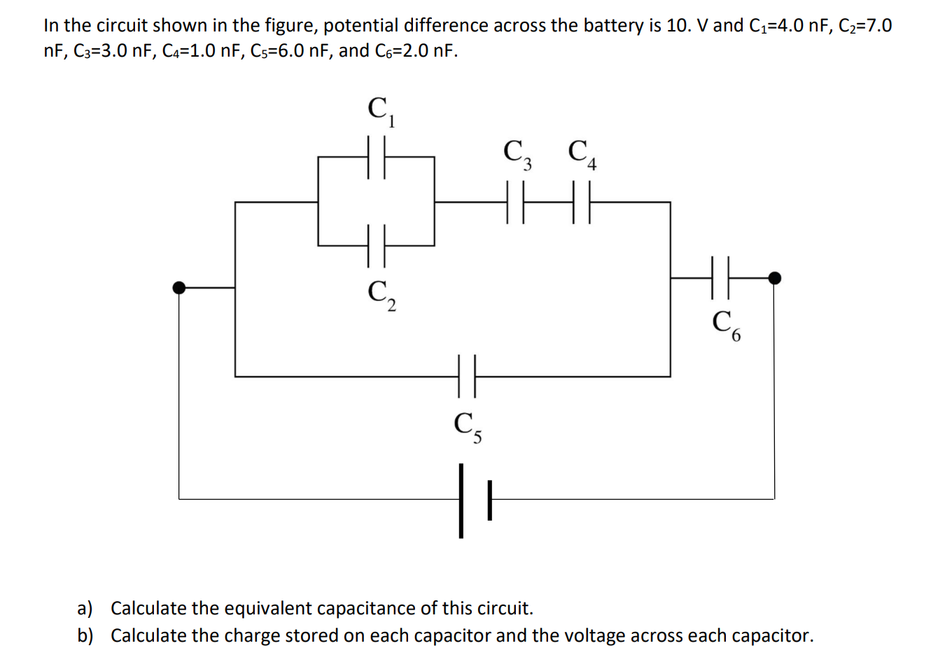
In the circuit shown in the figure, potential difference across the battery is 10. V and C₁=4.0 nF, C₂=7.0 nF, C3=3.0 nF, C4=1.0 nF, C5-6.0 nF, and C6-2.0 nF. C₁ C3 C₁ C₂ C6 C5 a) Calculate the equivalent capacitance of this circuit. b) Calculate the charge stored on each capacitor and the voltage across each capacitor.