Page 1 of 1
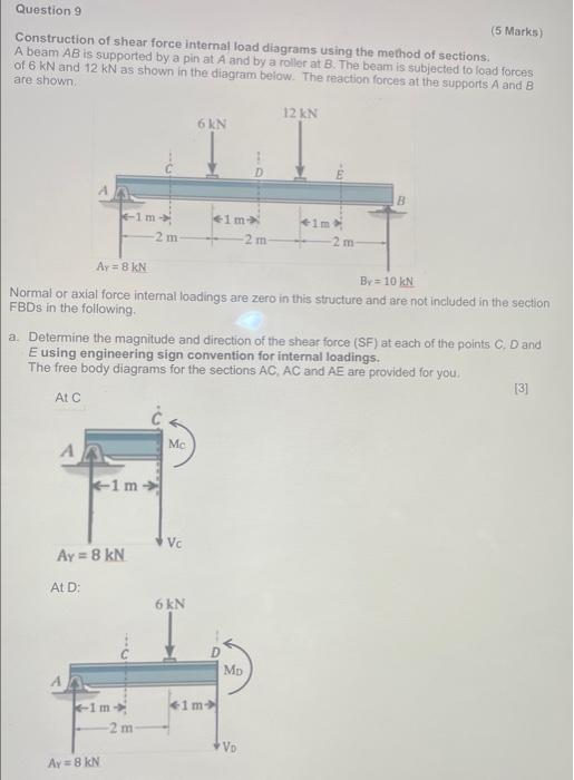
Question 9 (5 Marks) Construction of shear force internal load diagrams using the method of sections. A beam AB is suppo
Posted: Wed Jun 08, 2022 8:37 am
by answerhappygod
- Question 9 5 Marks Construction Of Shear Force Internal Load Diagrams Using The Method Of Sections A Beam Ab Is Suppo 1 (30.1 KiB) Viewed 45 times
- Question 9 5 Marks Construction Of Shear Force Internal Load Diagrams Using The Method Of Sections A Beam Ab Is Suppo 2 (21.46 KiB) Viewed 45 times
Question 9 (5 Marks) Construction of shear force internal load diagrams using the method of sections. A beam AB is supported by a pin at A and by a roller at B. The beam is subjected to load forces of 6 kN and 12 kN as shown in the diagram below. The reaction forces at the supports A and B are shown. 12 kN 6 kN B +1m* -1m 2 m 41m* 2 m- 2 m- Ay = 8 KN By=10 kN Normal or axial force internal loadings are zero in this structure and are not included in the section FBDs in the following. a. Determine the magnitude and direction of the shear force (SF) at each of the points C, D and E using engineering sign convention for internal loadings. The free body diagrams for the sections AC, AC and AE are provided for you. [3] At C Mc A -1 m Ay = 8 KN At D: K-1m Ay = 8 kN -2 m Vc 6 kN <1m> MD VD -1
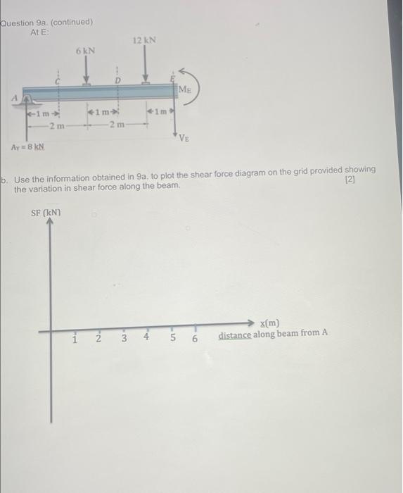
Question 9a. (continued) At E: 6 kN -1m +1m TH 2 12 kN w3 -2m 2 m VE Ay = 8 KN [2] b. Use the information obtained in 9a. to plot the shear force diagram on the grid provided showing the variation in shear force along the beam. SF (KN) x(m) distance along beam from A 1m mate ME