Page 1 of 1
As shown in the figure, the beam is supported by a pin support and a roller support at A and B, respectively. 12 kN/m B
Posted: Wed Jun 08, 2022 7:51 am
by answerhappygod
- As Shown In The Figure The Beam Is Supported By A Pin Support And A Roller Support At A And B Respectively 12 Kn M B 1 (104.33 KiB) Viewed 33 times
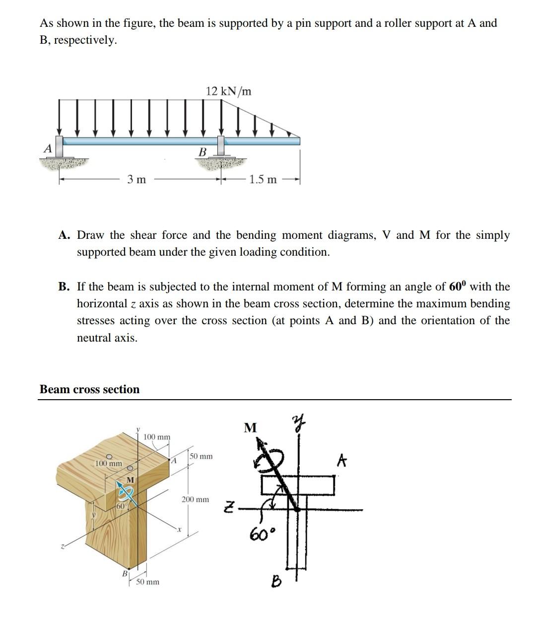
As shown in the figure, the beam is supported by a pin support and a roller support at A and B, respectively. 12 kN/m B 3 m 1.5 m A. Draw the shear force and the bending moment diagrams, V and M for the simply supported beam under the given loading condition. B. If the beam is subjected to the internal moment of M forming an angle of 60⁰ with the horizontal z axis as shown in the beam cross section, determine the maximum bending stresses acting over the cross section (at points A and B) and the orientation of the neutral axis. Beam cross section M y 100 mm 60 M B 100 mm 50 mm A 50 mm 200 mm 2. 60° B A