Page 1 of 1
Friction losses in a pipe Due to the pump in the water supply system shown in the figure below, the piezometric head dir
Posted: Wed Jun 08, 2022 7:12 am
by answerhappygod
- Friction Losses In A Pipe Due To The Pump In The Water Supply System Shown In The Figure Below The Piezometric Head Dir 1 (37.41 KiB) Viewed 63 times
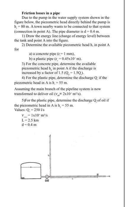
Friction losses in a pipe Due to the pump in the water supply system shown in the figure below, the piezometric head directly behind the pump is h = 80 m. A town nearby wants to be connected to that system (connection in point A). The pipe diameter is d = 0.4 m. 1) Draw the energy line (change of energy level) between the tank and point A into the figure. 2) Determine the available piezometric head h, in point A for a) a concrete pipe (ε = 1 mm). b) a plastic pipe (= 0.45x10¹ m). 3) For the concrete pipe, determine the available piezometric head h, in point A if the discharge is increased by a factor of 1.5 (Q₂ = 1.5Q). 4) For the plastic pipe, determine the discharge Q, if the piezometric head in A is h, = 55 m. Assuming the main branch of the pipeline system is now transformed to deliver oil (v=2x10 m²/s). 5)For the plastic pipe, determine the discharge Q, of oil if the piezometric head in A is h, = 55 m. Values: Q = 250 l/s V = 1x10¹ m²/s L = 2.5 km d = 0.4 m