Page 1 of 1
Problem 1 The diagram below shows a beam applied with a point force/load, a point moment/torque, and a distributed load.
Posted: Tue Jun 07, 2022 5:43 pm
by answerhappygod
- Problem 1 The Diagram Below Shows A Beam Applied With A Point Force Load A Point Moment Torque And A Distributed Load 1 (174.55 KiB) Viewed 62 times
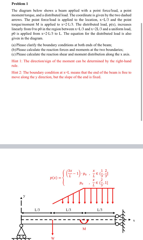
Problem 1 The diagram below shows a beam applied with a point force/load, a point moment/torque, and a distributed load. The coordinate is given by the two dashed arrows. The point force/load is applied to the location, x=L/3 and the point torque/moment M is applied to x-2-L/3. The distributed load, p(x), increases linearly from 0 to p0 in the region between x-L/3 and x=2L/3 and a uniform load, p0 is applied from x=2 L/3 to L. The equation for the distributed load is also given in the diagram. (a) Please clarify the boundary conditions at both ends of the beam; (b) Please calculate the reaction forces and moments at the two boundaries; (c) Please calculate the reaction shear and moment distribution along the x axis. Hint 1: The direction/sign of the moment can be determined by the right-hand rule. Hint 2: The boundary condition at x-L means that the end of the beam is free to move along the y direction, but the slope of the end is fixed. X 1 ((Z-1). Po x Po ZE(3,1] L/3 | L/3 p(x): W L/3 } U M