Page 1 of 1
For the beam illustrated in the figure, find the locations and magnitudes of the maximum tensile bending stress due to M
Posted: Tue Jun 07, 2022 5:33 pm
by answerhappygod
- For The Beam Illustrated In The Figure Find The Locations And Magnitudes Of The Maximum Tensile Bending Stress Due To M 1 (35.99 KiB) Viewed 78 times
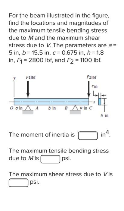
For the beam illustrated in the figure, find the locations and magnitudes of the maximum tensile bending stress due to M and the maximum shear stress due to V. The parameters are a = 5 in, b= 15.5 in, c = 0.675 in, h = 1.8 in, F₁ = 2800 lbf, and F2 = 1100 lbf. Filbf F21bf 0 G in A b in Bain C h in The moment of inertia is in4 The maximum tensile bending stress due to Mis psi. The maximum shear stress due to Vis psi. cin