Page 1 of 1
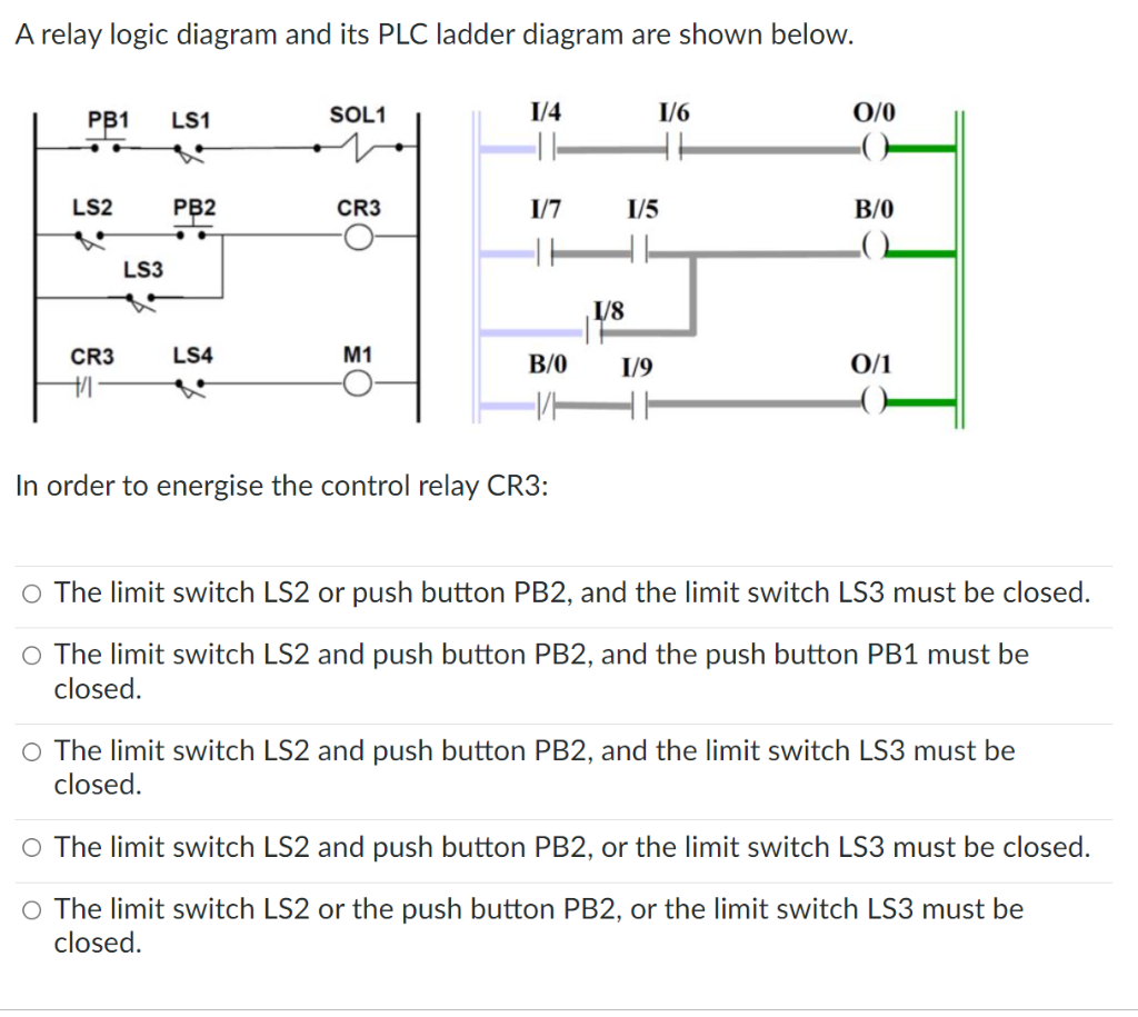
A relay logic diagram and its PLC ladder diagram are shown below. SOL1 1/4 1/6 PB1 LS1 0/0 TH PB2 CR3 1/7 B/0 -- LS4 M1
Posted: Tue Jun 07, 2022 5:14 pm
by answerhappygod
- A Relay Logic Diagram And Its Plc Ladder Diagram Are Shown Below Sol1 1 4 1 6 Pb1 Ls1 0 0 Th Pb2 Cr3 1 7 B 0 Ls4 M1 1 (261.58 KiB) Viewed 54 times
A relay logic diagram and its PLC ladder diagram are shown below. SOL1 1/4 1/6 PB1 LS1 0/0 TH PB2 CR3 1/7 B/0 -- LS4 M1 B/0 1/9 0/1 +/ In order to energise the control relay CR3: O The limit switch LS2 or push button PB2, and the limit switch LS3 must be closed. O The limit switch LS2 and push button PB2, and the push button PB1 must be closed. O The limit switch LS2 and push button PB2, and the limit switch LS3 must be closed. O The limit switch LS2 and push button PB2, or the limit switch LS3 must be closed. O The limit switch LS2 or the push button PB2, or the limit switch LS3 must be closed. LS2 CR3 LS3 1/8 1/5