Page 1 of 1
ME344 Control systems 1 The Project Consider the diagram in Figure 1 showing a motor drives an inertia load through a ge
Posted: Tue Jun 07, 2022 3:31 pm
by answerhappygod
- Me344 Control Systems 1 The Project Consider The Diagram In Figure 1 Showing A Motor Drives An Inertia Load Through A Ge 1 (44.45 KiB) Viewed 53 times
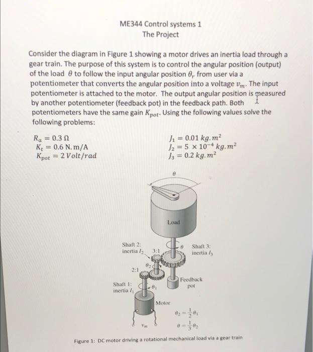
ME344 Control systems 1 The Project Consider the diagram in Figure 1 showing a motor drives an inertia load through a gear train. The purpose of this system is to control the angular position (output) of the load to follow the input angular position 8, from user via a potentiometer that converts the angular position into a voltage vm. The input potentiometer is attached to the motor. The output angular position is measured by another potentiometer (feedback pot) in the feedback path. Both potentiometers have the same gain Kpot- Using the following values solve the following problems: Ra=0.30 K = 0.6 N. m/A Kpot = 2 Volt/rad J₁ = 0.01 kg.m² J2 = 5 x 10⁴ kg.m² J3 = 0.2 kg. m² Load & Shaft 2: inertia /₂ 2:1 3:1 820 Shaft 3: inertia / 8₁ Shaft 1: inertia /₁ Feedback pot Motor Figure 1: DC motor driving a rotational mechanical load via a gear traini