Page 1 of 1
Final Exam s2-2021 Student Name: 20/4/2021 (Time: 30 min) Q# 3: A- the schematic diagram below is for Single duct, varia
Posted: Tue Jun 07, 2022 2:08 pm
by answerhappygod
- Final Exam S2 2021 Student Name 20 4 2021 Time 30 Min Q 3 A The Schematic Diagram Below Is For Single Duct Varia 1 (53.1 KiB) Viewed 48 times
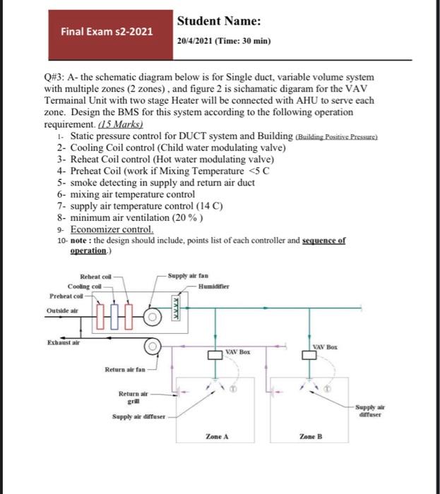
Final Exam s2-2021 Student Name: 20/4/2021 (Time: 30 min) Q# 3: A- the schematic diagram below is for Single duct, variable volume system with multiple zones (2 zones), and figure 2 is sichamatic digaram for the VAV Termainal Unit with two stage Heater will be connected with AHU to serve each zone. Design the BMS for this system according to the following operation requirement. (15 Marks) 1- Static pressure control for DUCT system and Building (Building Positive Pressure) 2- Cooling Coil control (Child water modulating valve) 3- Reheat Coil control (Hot water modulating valve) 4- Preheat Coil (work if Mixing Temperature <5 C 5- smoke detecting in supply and return air duct 6- mixing air temperature control 7- supply air temperature control (14 C) 8- minimum air ventilation (20 %) 9- Economizer control. 10- note: the design should include, points list of each controller and sequence of operation.) -Supply air fan Reheat coll Cooling coll -Humidifier Preheat coll Outside air STAMS VAV Box Return air fan Return air grill Supply air diffuser VAV Box Zone A Zone B Supply air diffuser