Page 1 of 1
2. Shafts in Figure 2 are connected by gear E (radius E= 100 mm) and F (radius r) at one end while the other ends are at
Posted: Tue Jun 07, 2022 1:35 pm
by answerhappygod
- 2 Shafts In Figure 2 Are Connected By Gear E Radius E 100 Mm And F Radius R At One End While The Other Ends Are At 1 (206.47 KiB) Viewed 55 times
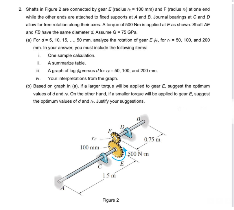
2. Shafts in Figure 2 are connected by gear E (radius E= 100 mm) and F (radius r) at one end while the other ends are attached to fixed supports at A and B. Journal bearings at C and D allow for free rotation along their axes. A torque of 500 Nm is applied at E as shown. Shaft AE and FB have the same diameter d. Assume G = 75 GPa. (a) For d = 5, 10, 15, ..., 50 mm, analyze the rotation of gear E E, for r = 50, 100, and 200 mm. In your answer, you must include the following items: i. One sample calculation. ii. A summarize table. iii. A graph of log E versus d for r = 50, 100, and 200 mm. iv. Your interpretations from the graph. (b) Based on graph in (a), if a larger torque will be applied to gear E, suggest the optimum values of d and rf. On the other hand, if a smaller torque will be applied to gear E, suggest the optimum values of d and rf. Justify your suggestions. TF 0.75 m 100 mm C 1.5 m Figure 2 E 500 N·m