Page 1 of 1
STEP 2 After completely discharging a 100μF capacitor, connect it to your circuit at C1, parallel to the buzzer, as show
Posted: Tue Jun 07, 2022 12:45 pm
by answerhappygod
- 1 (69.79 KiB) Viewed 35 times
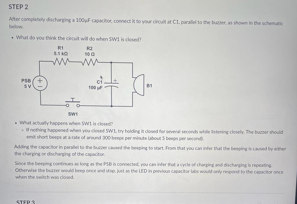
STEP 2 After completely discharging a 100μF capacitor, connect it to your circuit at C1, parallel to the buzzer, as shown in the schematic below. • What do you think the circuit will do when SW1 is closed? R2 R1 5.1 ΚΩ 10 Q PSB + 5 V C1 100 μF B1 SW1 • What actually happens when SW1 is closed? . If nothing happened when you closed SW1, try holding it closed for several seconds while listening closely. The buzzer should emit short beeps at a rate of around 300 beeps per minute (about 5 beeps per second). Adding the capacitor in parallel to the buzzer caused the beeping to start. From that you can infer that the beeping is caused by either the charging or discharging of the capacitor. Since the beeping continues as long as the PSB is connected, you can infer that a cycle of charging and discharging is repeating. Otherwise the buzzer would beep once and stop, just as the LED in previous capacitor labs would only respond to the capacitor once when the switch was closed. STEP 3