Page 1 of 1
4) Problem 4: For the circuit in Figure 3, use the following parameters: NMOS PMOS uCox (uA/V²) 80 20 0.5 -0.5 VT (V) (V
Posted: Tue Jun 07, 2022 11:53 am
by answerhappygod
- 4 Problem 4 For The Circuit In Figure 3 Use The Following Parameters Nmos Pmos Ucox Ua V 80 20 0 5 0 5 Vt V V 1 (53.08 KiB) Viewed 46 times
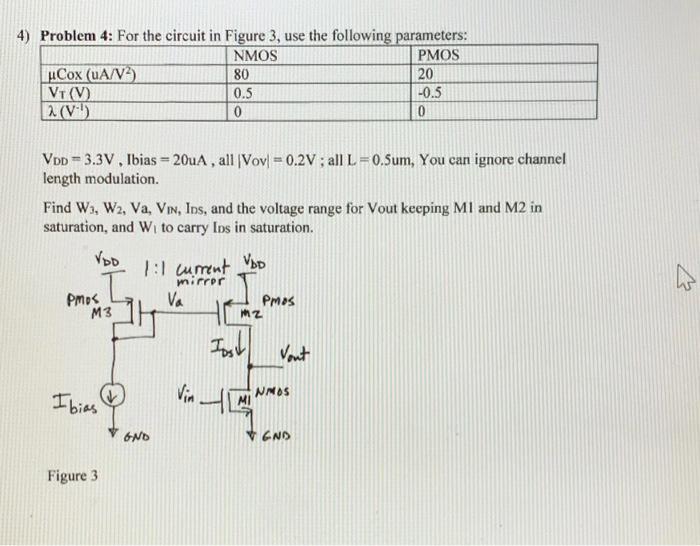
4) Problem 4: For the circuit in Figure 3, use the following parameters: NMOS PMOS uCox (uA/V²) 80 20 0.5 -0.5 VT (V) (V¹) 0 0 T VDD 3.3V, Ibias = 20uA, all (Vov) = 0.2V; all L=0.5um, You can ignore channel length modulation. Find W₁, W2, Va, VIN, Ins, and the voltage range for Vout keeping M1 and M2 in saturation, and W₁ to carry Ins in saturation. VDD 1:1 current VDD mirror PMOS Va Pmos M3 Ibias Figure 3 GND Vin MZ Jost MI Vont NMOS END ✩