Page 1 of 1
Question # 1 (20 points) SHOW YOUR CALCULATIONS The system diagram shown below shows a simple 132 kV network. It is requ
Posted: Tue Jun 07, 2022 11:08 am
by answerhappygod
- Question 1 20 Points Show Your Calculations The System Diagram Shown Below Shows A Simple 132 Kv Network It Is Requ 1 (56.47 KiB) Viewed 40 times
- Question 1 20 Points Show Your Calculations The System Diagram Shown Below Shows A Simple 132 Kv Network It Is Requ 2 (40.14 KiB) Viewed 40 times
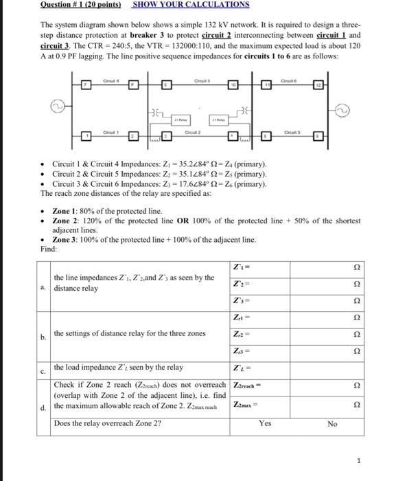
Question # 1 (20 points) SHOW YOUR CALCULATIONS The system diagram shown below shows a simple 132 kV network. It is required to design a three- step distance protection at breaker 3 to protect circuit 2 interconnecting between circuit 1 and circuit 3. The CTR=240:5, the VTR = 132000:110, and the maximum expected load is about 120 A at 0.9 PF lagging. The line positive sequence impedances for circuits 1 to 6 are as follows: C4 Onuit C1 Cut 0 0 Circuit 1 & Circuit 4 Impedances: Z₁ = 35.2284°2=Z. (primary). Circuit 2 & Circuit 5 Impedances: Z₂-35.1284° 2-Zs (primary). Circuit 3 & Circuit 6 Impedances: Z3 = 17.6284° 2=Z6 (primary). The reach zone distances of the relay are specified as: • Zone 1: 80% of the protected line. • Zone 2: 120% of the protected line OR 100% of the protected line + 50% of the shortest adjacent lines. Zone 3: 100% of the protected line + 100% of the adjacent line. Find: Z₁= the line impedances Z₁, Z2,and Z's as seen by the distance relay Z':= a. Z's= Z₁ = the settings of distance relay for the three zones Z₁2= b. Z₁3= the load impedance Z't seen by the relay ZL- Check if Zone 2 reach (Z2reach) does not overreach Z2reach= (overlap with Zone 2 of the adjacent line), i.e. find d. the maximum allowable reach of Zone 2. Z2max reach Z2max= Does the relay overreach Zone 2? Yes Cut 3 No a 22 22 52 52 52 52 la S2
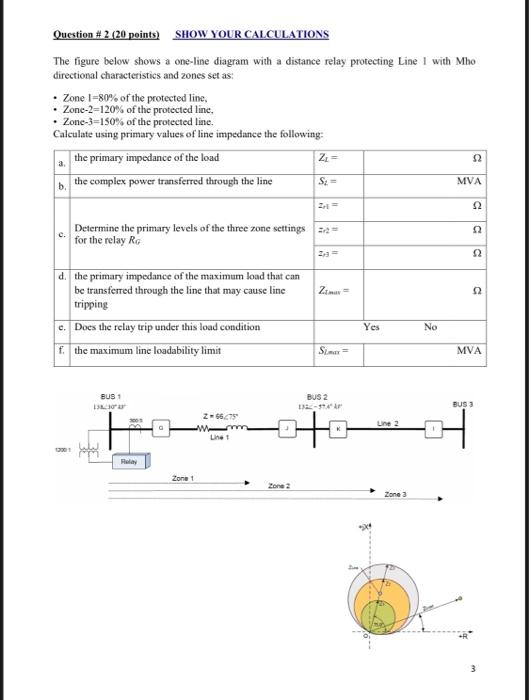
Question # 2 (20 points) SHOW YOUR CALCULATIONS The figure below shows a one-line diagram with a distance relay protecting Line 1 with Mho directional characteristics and zones set as: • Zone 1-80% of the protected line, • Zone-2-120% of the protected line. • Zone-3-150% of the protected line. Calculate using primary values of line impedance the following: the primary impedance of the load Z₁ = 52 the complex power transferred through the line St= MVA 52 Determine the primary levels of the three zone settings 2 for the relay RG d. the primary impedance of the maximum load that can Zimax= be transferred through the line that may cause line tripping e. Does the relay trip under this load condition f. the maximum line loadability limit Simax= BUS 1 13:30 12001 You Relay Zone 1 Z-6675" Line 1 Zone 2 BUS 2 132-37A² AP Yes Line 2 Zone 3 No C 22 22 52 MVA BUS 3