Page 1 of 1
4.16. The variable resistor R, in the circuit in Fig. P4.16 is adjusted until the source current ig is zero. The op amps
Posted: Tue Jun 07, 2022 10:35 am
by answerhappygod
- 4 16 The Variable Resistor R In The Circuit In Fig P4 16 Is Adjusted Until The Source Current Ig Is Zero The Op Amps 1 (83.71 KiB) Viewed 29 times
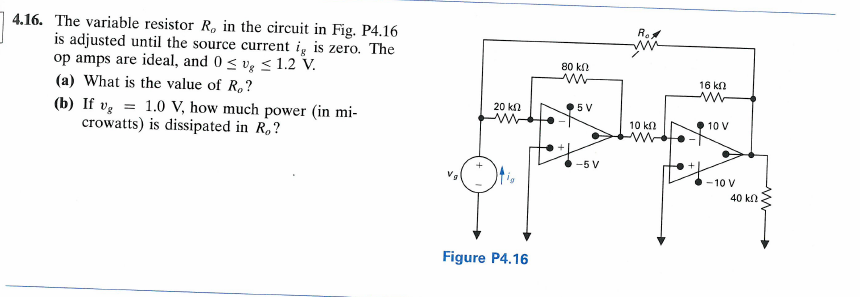
4.16. The variable resistor R, in the circuit in Fig. P4.16 is adjusted until the source current ig is zero. The op amps are ideal, and 0 ≤ vg ≤ 1.2 V. (a) What is the value of R₂? (b) If vg = 1.0 V, how much power (in mi- crowatts) is dissipated in Ro? 20 ΚΩ www Figure P4.16 80 ΚΩ 5 V -5 V Ro 10 k 16 ΚΩ ww 10 V -10 V 40 ΚΩ