Page 1 of 1
b) Consider the continuous closed loop control system shown in Figure 6. In this system, the control signal that is appl
Posted: Tue Jun 07, 2022 10:34 am
by answerhappygod
- B Consider The Continuous Closed Loop Control System Shown In Figure 6 In This System The Control Signal That Is Appl 1 (43.72 KiB) Viewed 35 times
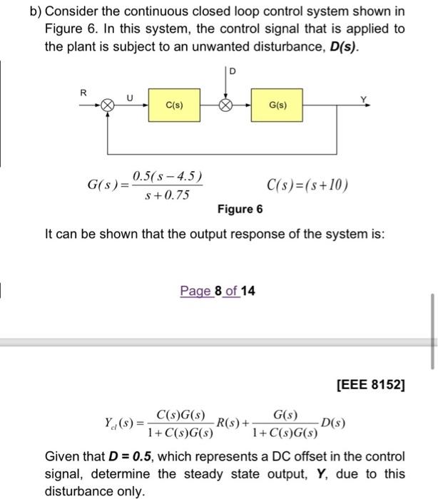
b) Consider the continuous closed loop control system shown in Figure 6. In this system, the control signal that is applied to the plant is subject to an unwanted disturbance, D(s). D R D'O C(s) G(s) 0.5(s-4.5) G(s) = C(s)=(s+10) s+0.75 Figure 6 It can be shown that the output response of the system is: Page 8 of 14 [EEE 8152] G(s) Y(s) = C(s)G(s) 1+ C(s)G(s) -R(s) + -D(s) 1+ C(s)G(s) Given that D = 0.5, which represents a DC offset in the control signal, determine the steady state output, Y, due to this disturbance only.