Page 1 of 1
Question 4 In the circuit shown in Figure 3 below, V₁ = 0.1 sin (2 x 8000 t). Design a DC shifting and amplifier circuit
Posted: Tue Jun 07, 2022 9:59 am
by answerhappygod
- Question 4 In The Circuit Shown In Figure 3 Below V 0 1 Sin 2 X 8000 T Design A Dc Shifting And Amplifier Circuit 1 (39.69 KiB) Viewed 64 times
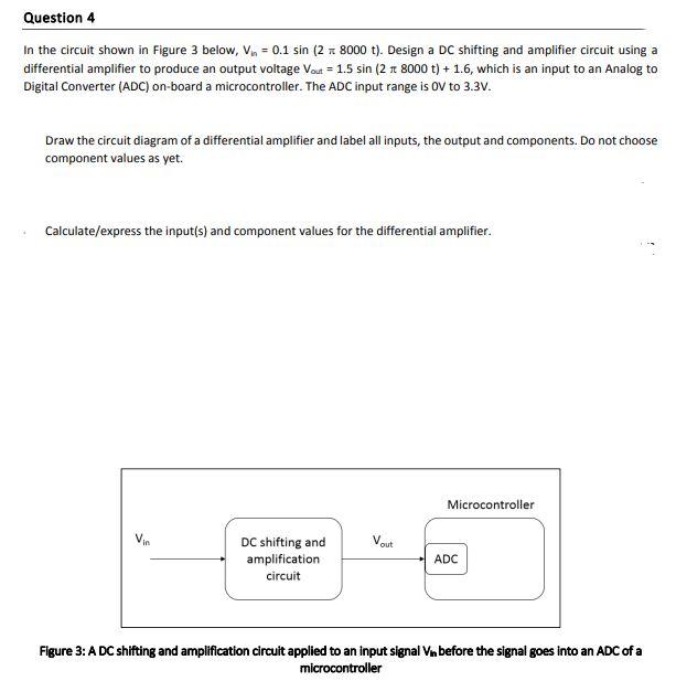
Question 4 In the circuit shown in Figure 3 below, V₁ = 0.1 sin (2 x 8000 t). Design a DC shifting and amplifier circuit using a differential amplifier to produce an output voltage Vout = 1.5 sin (2 rt 8000 t) + 1.6, which is an input to an Analog to Digital Converter (ADC) on-board a microcontroller. The ADC input range is OV to 3.3V. Draw the circuit diagram of a differential amplifier and label all inputs, the output and components. Do not choose component values as yet. Calculate/express the input(s) and component values for the differential amplifier. Microcontroller Vout DC shifting and amplification circuit ADC Figure 3: A DC shifting and amplification circuit applied to an input signal Vin before the signal goes into an ADC of a microcontroller