Page 1 of 1
Question 9 9.1 Figure 8 shows a BJT-based current mirror where Q₂ has a base-emitter junction area twice that of Q₁. JUE
Posted: Tue Jun 07, 2022 9:58 am
by answerhappygod
- Question 9 9 1 Figure 8 Shows A Bjt Based Current Mirror Where Q Has A Base Emitter Junction Area Twice That Of Q Jue 1 (34.08 KiB) Viewed 64 times
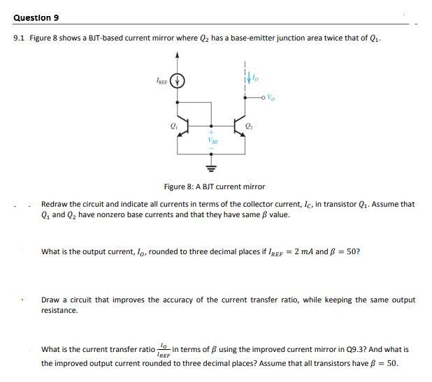
Question 9 9.1 Figure 8 shows a BJT-based current mirror where Q₂ has a base-emitter junction area twice that of Q₁. JUEF 2₁ l₂ Figure 8: A BJT current mirror Redraw the circuit and indicate all currents in terms of the collector current, Ic, in transistor Q₁. Assume that Q₁ and Q₂ have nonzero base currents and that they have same ß value. What is the output current, Io, rounded to three decimal places if IREF = 2 mA and B = 50? Draw a circuit that improves the accuracy of the current transfer ratio, while keeping the same output resistance. What is the current transfer ratio in terms of using the improved current mirror in Q9.3? And what is IREF the improved output current rounded to three decimal places? Assume that all transistors have = 50.