Page 1 of 1
Hard Question 6) Laplace in Circuits and Frequency Response R₁ -0 www V₂ Figure 5: (a) Gyrator circuit. (b) RL-circuit.
Posted: Tue Jun 07, 2022 9:57 am
by answerhappygod
- Hard Question 6 Laplace In Circuits And Frequency Response R 0 Www V Figure 5 A Gyrator Circuit B Rl Circuit 1 (265.82 KiB) Viewed 66 times
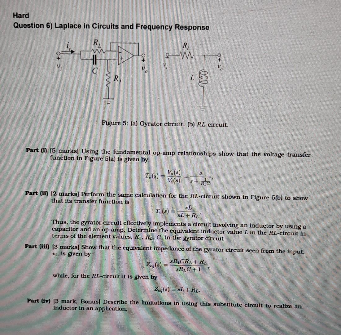
Hard Question 6) Laplace in Circuits and Frequency Response R₁ -0 www V₂ Figure 5: (a) Gyrator circuit. (b) RL-circuit. Part (1) (5 marks] Using the fundamental op-amp relationships show that the voltage transfer function in Figure 5(a) is given by. S T-(s) = V.(s) V.(s) S+RC Part (ii) [2 marks] Perform the same calculation for the RL-circuit shown in Figure 5(b) to show that its transfer function is T,(s) = SL SL + R Thus, the gyrator circult effectively implements a circuit involving an inductor by using a capacitor and an op-amp. Determine the equivalent inductor value L in the RL-circuit in terms of the element values, R₁. R. C, in the gyrator circuit Part (iii) [3 marks] Show that the equivalent impedance of the gyrator circuit seen from the input, U₁. is given by SR₂CR₂RL SRLC +1 while, for the RL-circuit it is given by Zeg(s)=L+RL Part (iv) [3 mark, Bonus] Describe the limitations in using this substitute circult to realize an inductor in an application. ell