Page 1 of 1
For the half-wave uncontrolled rectifier circuit supplying a series resistive- inductive load shown in Fig.2.35. The sup
Posted: Tue Jun 07, 2022 9:52 am
by answerhappygod
- For The Half Wave Uncontrolled Rectifier Circuit Supplying A Series Resistive Inductive Load Shown In Fig 2 35 The Sup 1 (104.43 KiB) Viewed 59 times
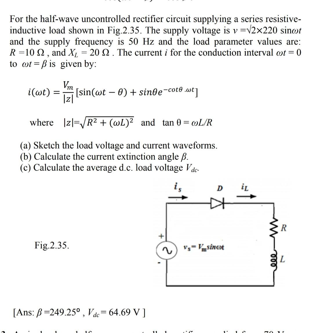
For the half-wave uncontrolled rectifier circuit supplying a series resistive- inductive load shown in Fig.2.35. The supply voltage is v =√2×220 sinot and the supply frequency is 50 Hz and the load parameter values are: R=10 Q2, and X₂ = 20 2. The current i for the conduction interval oot = = 0 to wtß is given by: = Vm i(wt) = = [sin(wt − 0) + sin0e¬coto 0.wt] |z| where |z√ √R² + (wL)² and tan 0 = @L/R (a) Sketch the load voltage and current waveforms. (b) Calculate the current extinction angle ß. (c) Calculate the average d.c. load voltage Vdc- is Fig.2.35. [Ans: B=249.25°, Vdc=64.69 V ] D iL VsVmsinot eee 50 R L