Page 1 of 1
1. Design and develop an equivalent circuit of transformer as shown in Figure 1 by using MULTISIM. 2. With the value R1-
Posted: Tue Jun 07, 2022 9:50 am
by answerhappygod
- 1 Design And Develop An Equivalent Circuit Of Transformer As Shown In Figure 1 By Using Multisim 2 With The Value R1 1 (40.07 KiB) Viewed 47 times
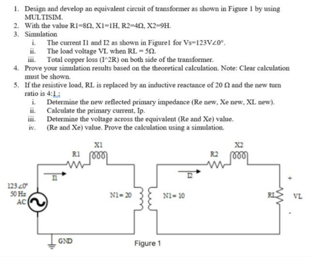
1. Design and develop an equivalent circuit of transformer as shown in Figure 1 by using MULTISIM. 2. With the value R1-802, X1-1H, R2-402, X2=9H. 3. Simulation i. The current II and 12 as shown in Figurel for Vs-123VZ0°. The load voltage VL when RL = 50. ii. iii. Total copper loss (I^2R) on both side of the transformer. 4. Prove your simulation results based on the theoretical calculation. Note: Clear calculation must be shown. 5. If the resistive load, RL is replaced by an inductive reactance of 20 2 and the new turn ratio is 4:1: i. Determine the new reflected primary impedance (Re new, Xe new, XL new). Calculate the primary current, Ip. ii. iii. Determine the voltage across the equivalent (Re and Xe) value. (Re and Xe) value. Prove the calculation using a simulation. iv. XI X2 R1 00 R2 N1=20 N1=10 123 20 50 Hz AC GND Figure 1 RL VL