Page 1 of 1
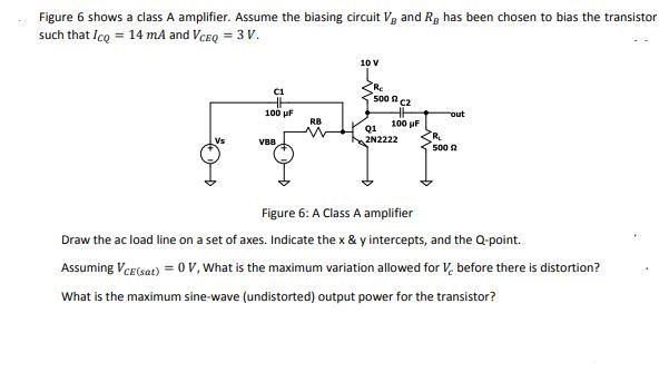
Figure 6 shows a class A amplifier. Assume the biasing circuit V, and R, has been chosen to bias the transistor such tha
Posted: Tue Jun 07, 2022 9:18 am
by answerhappygod
- Figure 6 Shows A Class A Amplifier Assume The Biasing Circuit V And R Has Been Chosen To Bias The Transistor Such Tha 1 (23.84 KiB) Viewed 33 times
Figure 6 shows a class A amplifier. Assume the biasing circuit V, and R, has been chosen to bias the transistor such that Icq = 14 mA and VCEQ = 3 V. 10 V C1 100 μF out RB Q1 2N2222 R₂ V88 500 2 Figure 6: A Class A amplifier Draw the ac load line on a set of axes. Indicate the x & y intercepts, and the Q-point. Assuming VCE(sat) = 0 V, What is the maximum variation allowed for V, before there is distortion? What is the maximum sine-wave (undistorted) output power for the transistor? Re 5002 CZ 100 pF