Page 1 of 1
Question 5 In the circuit shown in Figure 4 below, Vin = 24 V and R, = 800 52. All the other component values need to be
Posted: Tue Jun 07, 2022 9:17 am
by answerhappygod
- Question 5 In The Circuit Shown In Figure 4 Below Vin 24 V And R 800 52 All The Other Component Values Need To Be 1 (58.04 KiB) Viewed 65 times
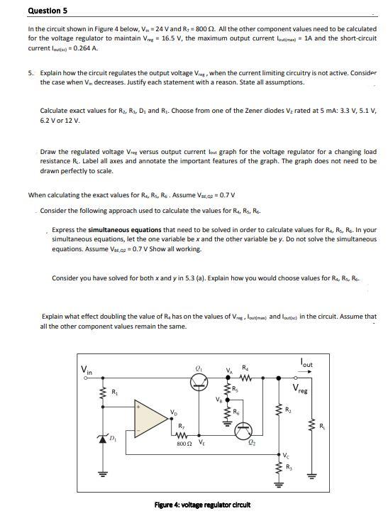
Question 5 In the circuit shown in Figure 4 below, Vin = 24 V and R, = 800 52. All the other component values need to be calculated for the voltage regulator to maintain V = 16.5 V, the maximum output current loutimax) = 1A and the short-circuit current loutis) = 0.264 A. 5. Explain how the circuit regulates the output voltage V, when the current limiting circuitry is not active. Consider the case when V., decreases. Justify each statement with a reason. State all assumptions. Calculate exact values for R₂, R₁, D₁ and R₁. Choose from one of the Zener diodes V₂ rated at 5 mA: 3.3 V, 5.1 V, 6.2 V or 12 V. Draw the regulated voltage Vreg versus output current lout graph for the voltage regulator for a changing load resistance R₁. Label all axes and annotate the important features of the graph. The graph does not need to be drawn perfectly to scale. When calculating the exact values for Ra, R₁, R. Assume Var,02 = 0.7 V Consider the following approach used to calculate the values for R₁, Rs, R. Express the simultaneous equations that need to be solved in order to calculate values for R₁, R₁, R. In your simultaneous equations, let the one variable be x and the other variable be y. Do not solve the simultaneous equations. Assume Vst,q2 = 0.7 V Show all working. Consider you have solved for both x and y in 5.3 (a). Explain how you would choose values for R4, R₁, Ro- Explain what effect doubling the value of R, has on the values of Viegloutman) and loutc) in the circuit. Assume that all the other component values remain the same. lout Vin 2₁ R₂ D₁ Vo R₂ www 85 www. www Or 8002 V Figure 4: voltage regulator circult www Vres R₂ Vc ww +₁ R₁