Page 1 of 1
The timing diagram below is for a button press synchronizer that synchronizes a button press to a clock signal. The circ
Posted: Mon Jun 06, 2022 7:28 pm
by answerhappygod
- The Timing Diagram Below Is For A Button Press Synchronizer That Synchronizes A Button Press To A Clock Signal The Circ 1 (25.06 KiB) Viewed 55 times
- The Timing Diagram Below Is For A Button Press Synchronizer That Synchronizes A Button Press To A Clock Signal The Circ 2 (28.44 KiB) Viewed 55 times
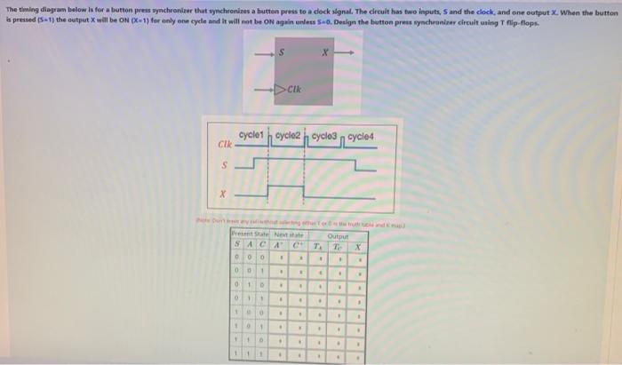
The timing diagram below is for a button press synchronizer that synchronizes a button press to a clock signal. The circuit has two inputs, S and the clock, and one output X. When the button is pressed (5-1) the output X will be ON (X-1) for only one cycle and it will not be ON again unless 5-0, Design the button press synchronizer circuit using T flip-flops. S X Cik cycle2 cycle3 cycle4 cycle1 Cik S X Dney Present State Next state SACAC T " " 000 00 . 010 . . 4 " . . 11 . . . . 10 0 . . 1. 1 0 1 . . . 1 1 6 . 1 1 00 010 1 ng other or the truth and Output T X . 4 . . . * . . . . . . . A 1 1 . "
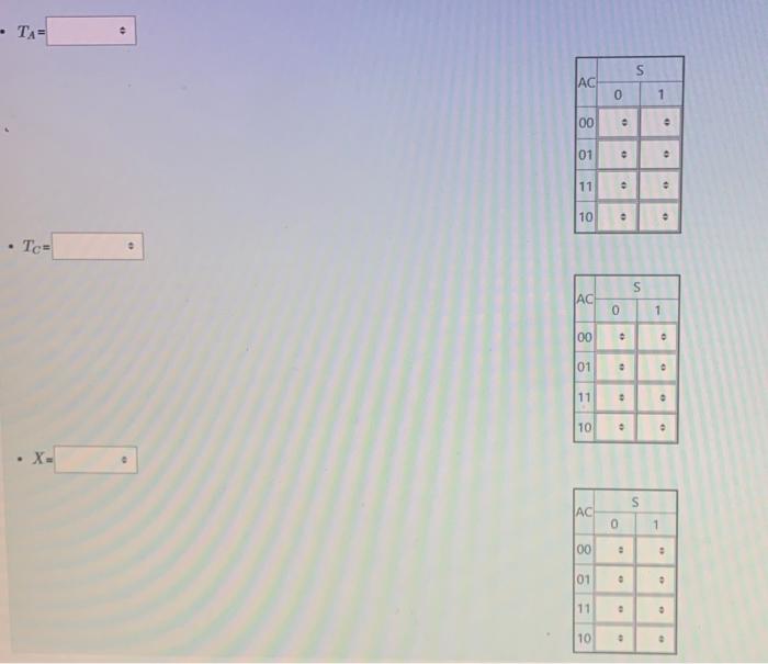
TA= Tc- · X- 0 AC 00 0 01 11 10 AC 00 01 11 10 AC 00 01 11 10 0 # • " 0 0 0 o 0 S 2 0 0 • S 1 S " ● 1 ● 0 ● • 0 0 1 o # o 0 "