Page 1 of 1
Design a Traffic Light Controller (TLC) digital circuit which will operate in the following sequence: Red, Red, Red Yell
Posted: Mon Jun 06, 2022 7:26 pm
by answerhappygod
- Design A Traffic Light Controller Tlc Digital Circuit Which Will Operate In The Following Sequence Red Red Red Yell 1 (78.82 KiB) Viewed 52 times
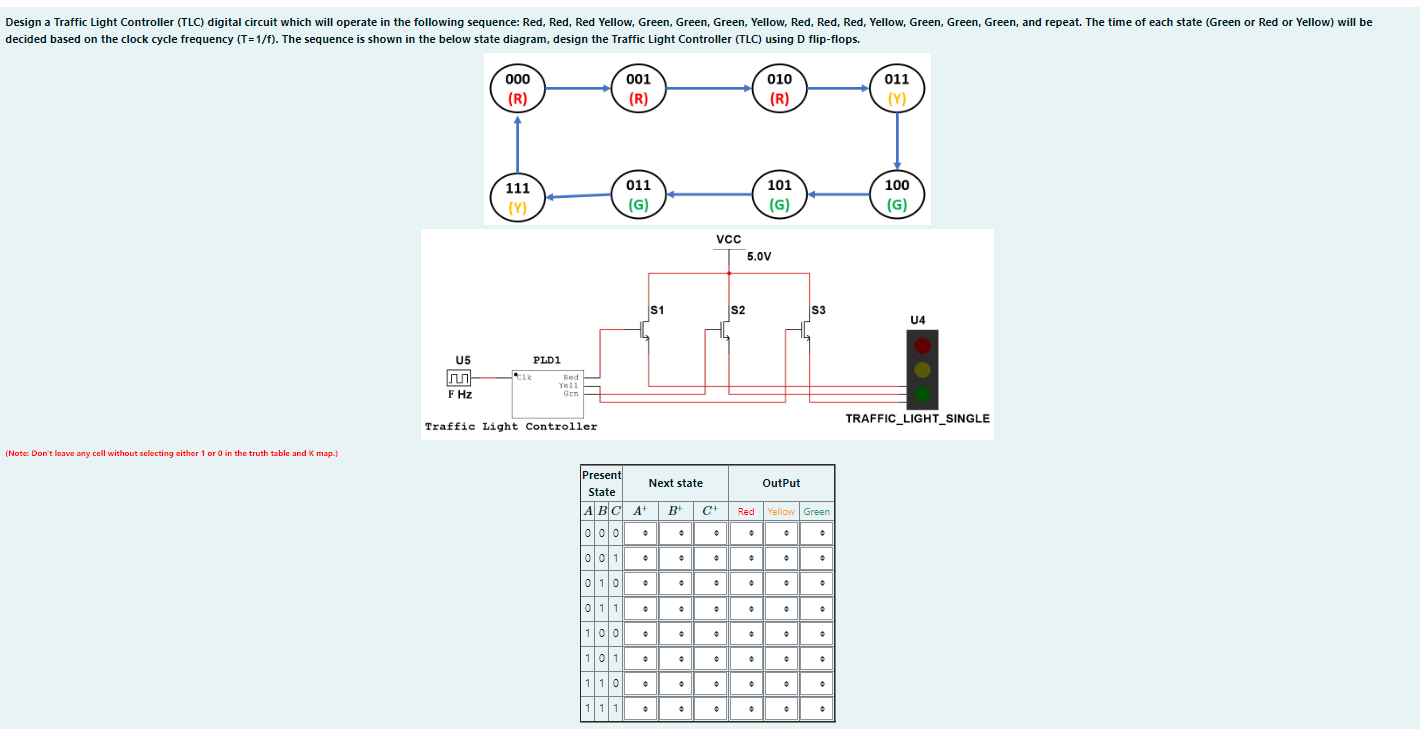
Design a Traffic Light Controller (TLC) digital circuit which will operate in the following sequence: Red, Red, Red Yellow, Green, Green, Green, Yellow, Red, Red, Red, Yellow, Green, Green, Green, and repeat. The time of each state (Green or Red or Yellow) will be decided based on the clock cycle frequency (T=1/f). The sequence is shown in the below state diagram, design the Traffic Light Controller (TLC) using D flip-flops. 000 001 010 011 (R) (R) (R) (Y) 111 011 101 100 (Y) (G) (G) (G) (Note: Don't leave any cell without selecting either 1 or 0 in the truth table and K map.) U5 Cik Red Yell F Hz Grn Traffic Light Controller PLD1 S1 • VCC • • + Present State Next state ABC A+ B+ C+ Red 000 • + • 001 JU 0 1 0 011 100 101 1 10 1 1 1 M + + |° 5.0V • S2 a • • Output Yellow Green • + S3 + • • • + U4 TRAFFIC_LIGHT_SINGLE
. DA= . Du . De • Red . Yellow . Green= * • Calculate the frequency of the clock if the Red signal should be ON for 300 seconds. f= Hz BC 00 01 11 10 BC 0 00 01 . 11 • 10 * |BC| 6|98|| 00 01 11 • • 10 + BC 8981 10 BC 100 01 11 10 BC 0 00 . 01 • 11 * • • 1816ES 0 10 0 • • . 0 00 . 01 • * • A A A A 0 1 A 1 A * 1 * 1 * * * * 1 . 1 *