Page 1 of 1
N₁ }|{ N₂ 30 Va Fig. Q5 1. A flyback converter shown in Fig.Q5 is operating in a complete demagnetization mode. Derive t
Posted: Mon Jun 06, 2022 7:04 pm
by answerhappygod
- N N 30 Va Fig Q5 1 A Flyback Converter Shown In Fig Q5 Is Operating In A Complete Demagnetization Mode Derive T 1 (188.29 KiB) Viewed 21 times
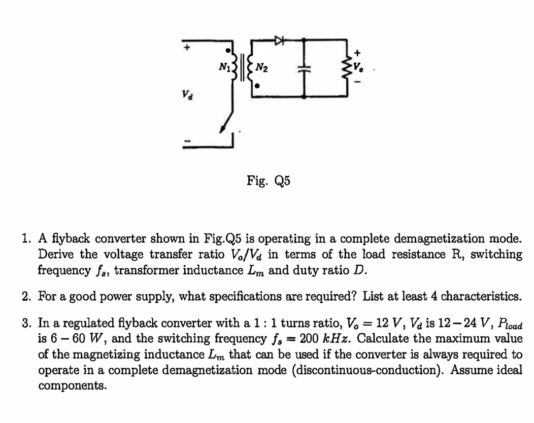
N₁ }|{ N₂ 30 Va Fig. Q5 1. A flyback converter shown in Fig.Q5 is operating in a complete demagnetization mode. Derive the voltage transfer ratio V/V in terms of the load resistance R, switching frequency fa, transformer inductance Lm and duty ratio D. 2. For a good power supply, what specifications are required? List at least 4 characteristics. 3. In a regulated flyback converter with a 1: 1 turns ratio, V = 12 V, V is 12-24 V, Pload is 6 - 60 W, and the switching frequency f, = 200 kHz. Calculate the maximum value of the magnetizing inductance Lm that can be used if the converter is always required to operate in a complete demagnetization mode (discontinuous-conduction). Assume ideal components.