Page 1 of 1
QUESTION 1 [100 marks] The circuit in Fig. 1(a) is a sensor readout circuit developed by MEMS/NEMS research group (simpl
Posted: Mon Jun 06, 2022 7:00 pm
by answerhappygod
- Question 1 100 Marks The Circuit In Fig 1 A Is A Sensor Readout Circuit Developed By Mems Nems Research Group Simpl 1 (70.12 KiB) Viewed 37 times
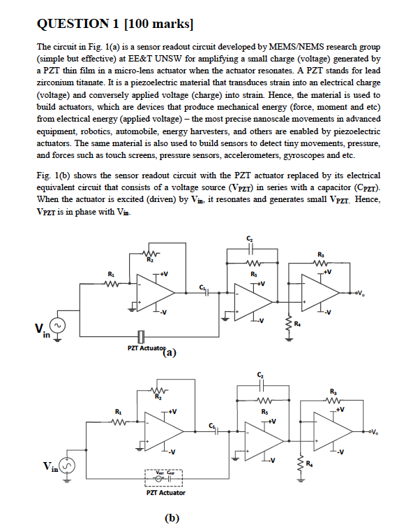
QUESTION 1 [100 marks] The circuit in Fig. 1(a) is a sensor readout circuit developed by MEMS/NEMS research group (simple but effective) at EE&T UNSW for amplifying a small charge (voltage) generated by a PZT thin film in a micro-lens actuator when the actuator resonates. A PZT stands for lead zirconium titanate. It is a piezoelectric material that transduces strain into an electrical charge (voltage) and conversely applied voltage (charge) into strain. Hence, the material is used to build actuators, which are devices that produce mechanical energy (force, moment and etc) from electrical energy (applied voltage) - the most precise nanoscale movements in advanced equipment, robotics, automobile, energy harvesters, and others are enabled by piezoelectric actuators. The same material is also used to build sensors to detect tiny movements, pressure, and forces such as touch screens, pressure sensors, accelerometers, gyroscopes and etc. Fig. 1(b) shows the sensor readout circuit with the PZT actuator replaced by its electrical equivalent circuit that consists of a voltage source (VPZT) in series with a capacitor (CPZT). When the actuator is excited (driven) by Vin, it resonates and generates small VPZT. Hence, VPZT is in phase with Vin R₂ R₂ ww R₁ R₂ V. -+V + PZT Actuator R₁ www (a) -+V VI Cam PZT Actuator (b) ST www Rs +V ww R₁ R₂ +V R₂ www +V *V₂ -V₂
PART 1 (Gain calculation and op-amp applications) [30 marks] (a) [P.C] Obtain the expression for the output voltage (V.) of the amplifier when the actuator is driven (excited) by an AC source Vin operating at a frequency oo. [Hint: apply superposition principle and express the sources and the capacitor in complex frequency]. [10 marks] (b) [D] The purpose the readout circuit is to amplify the VPZT and reject any output due to Vin (Vo due to Vin is to be zero). How can the purpose of the amplifier circuit be achieved based on your expression in (a)? 1 (c) [P.C] Assuming R₁ = R₁, C₁ = C₂ = Cpz and R₁ » [5 marks] obtain the expression for [10 marks] 7 WC₂ the gain of the amplifier (Vo/VPZT). (d) [HD] Could you suggest a modification to the readout circuit (or new altogether) that improves the gain of the amplifier and better achieve the purpose of the circuit. [5 marks]