Page 1 of 1
6. The circuit shown in Figure 1 has ve resistances and one applied voltage. Kirchhoff.s voltage law applied to each loo
Posted: Mon Jun 06, 2022 11:23 am
by answerhappygod
- 6 The Circuit Shown In Figure 1 Has Ve Resistances And One Applied Voltage Kirchhoff S Voltage Law Applied To Each Loo 1 (50.32 KiB) Viewed 85 times
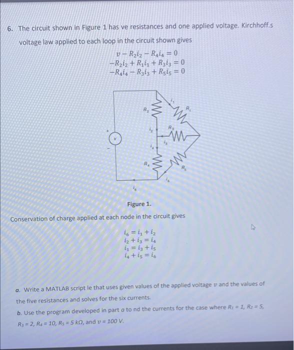
6. The circuit shown in Figure 1 has ve resistances and one applied voltage. Kirchhoff.s voltage law applied to each loop in the circuit shown gives v-R₂iz-Rai = 0 -R₂i₂ + R₁ + R313 = 0 -Rais-R3i3 + Rsis = 0 8₂ RA Figure 1. Conservation of charge applied at each node in the circuit gives 46 = 4₂ +1₂ 1₂ +13= 1₂ i₁ = 13 + is is + is = 16 a. Write a MATLAB script le that uses given values of the applied voltage and the values of the five resistances and solves for the six currents. b. Use the program developed in part a to nd the currents for the case where R: = 1, R₂ = 5, R₁=2, R₂ = 10, Rs=5 k0, and v= 100 V. As Ai