Page 1 of 1
Consider the converter in Figure C1 which operates with a supply voltage of 100 sin 60 V. G + R ~v=V sin at A FD L m ifa
Posted: Thu Jun 02, 2022 9:42 am
by answerhappygod
- Consider The Converter In Figure C1 Which Operates With A Supply Voltage Of 100 Sin 60 V G R V V Sin At A Fd L M Ifa 1 (31.69 KiB) Viewed 48 times
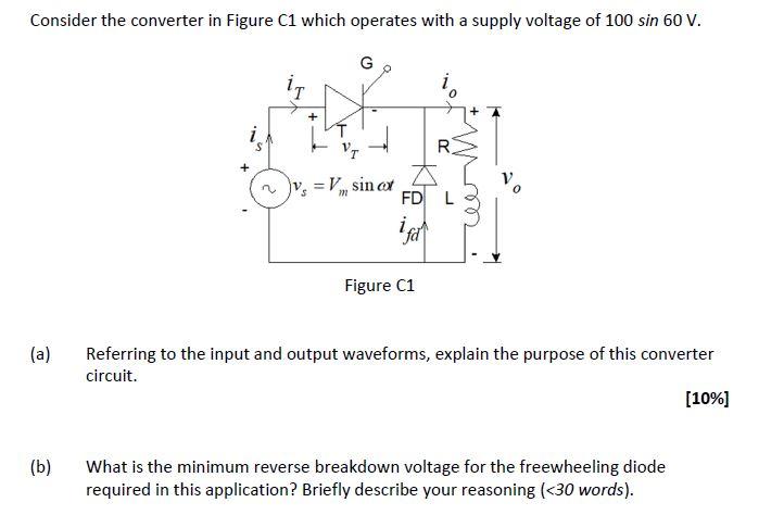
Consider the converter in Figure C1 which operates with a supply voltage of 100 sin 60 V. G + R ~v=V sin at A FD L m ifa Figure C1 (a) Referring to the input and output waveforms, explain the purpose of this converter circuit. [10%] (b) What is the minimum reverse breakdown voltage for the freewheeling diode required in this application? Briefly describe your reasoning (<30 words).