Page 1 of 1
1. Refer to the DC circuit shown in Figure 1 with the parameters V₂ = 120 V, R₂ = 100 ft. R₂ = 150 f, C = 100 µF. Assume
Posted: Thu Jun 02, 2022 9:36 am
by answerhappygod
- 1 Refer To The Dc Circuit Shown In Figure 1 With The Parameters V 120 V R 100 Ft R 150 F C 100 Uf Assume 1 (37.5 KiB) Viewed 62 times
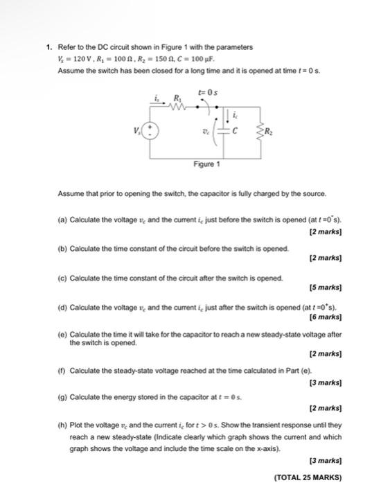
1. Refer to the DC circuit shown in Figure 1 with the parameters V₂ = 120 V, R₂ = 100 ft. R₂ = 150 f, C = 100 µF. Assume the switch has been closed for a long time and it is opened at time != 0s. t=0s De Figure 1 Assume that prior to opening the switch, the capacitor is fully charged by the source. (a) Calculate the voltage and the current i, just before the switch is opened (at t=0's). [2 marks] (b) Calculate the time constant of the circuit before the switch is opened. [2 marks] (c) Calculate the time constant of the circuit after the switch is opened. [5 marks] (d) Calculate the voltage and the current i, just after the switch is opened (at t=0*s). [6 marks] (e) Calculate the time it will take for the capacitor to reach a new steady-state voltage after the switch is opened. [2 marks] (f) Calculate the steady-state voltage reached at the time calculated in Part (e). [3 marks] (g) Calculate the energy stored in the capacitor at t=0 s. [2 marks] (h) Plot the voltage and the current i, for t> 0s. Show the transient response until they reach a new steady-state (Indicate clearly which graph shows the current and which graph shows the voltage and include the time scale on the x-axis). [3 marks] (TOTAL 25 MARKS)