Page 1 of 1
1 15 Table Q1 shows the truth-table of a priority encoder circuit with 4 inputs (D3, D2, D1 and D0) and two outputs (A1
Posted: Thu Jun 02, 2022 8:42 am
by answerhappygod
- 1 15 Table Q1 Shows The Truth Table Of A Priority Encoder Circuit With 4 Inputs D3 D2 D1 And D0 And Two Outputs A1 1 (58.82 KiB) Viewed 26 times
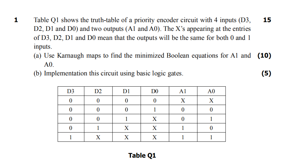
1 15 Table Q1 shows the truth-table of a priority encoder circuit with 4 inputs (D3, D2, D1 and D0) and two outputs (A1 and A0). The X's appearing at the entries of D3, D2, D1 and D0 mean that the outputs will be the same for both 0 and 1 inputs. (10) (a) Use Karnaugh maps to find the minimized Boolean equations for Al and A0. (b) Implementation this circuit using basic logic gates. (5) D3 D2 D1 DO A1 A0 0 0 0 0 X X 0 0 0 1 0 0 0 0 1 X 0 1 0 1 X X 1 0 1 X X X 1 1 Table Q1