Page 1 of 1
Vacuum Vacuum necessary beneficial Ejectors 15 20+ 10* 10 10* 10° 10° 10° 10 Permeability (m/s) 10' Figure 1 Range of ap
Posted: Fri May 27, 2022 7:40 am
by answerhappygod
- Vacuum Vacuum Necessary Beneficial Ejectors 15 20 10 10 10 10 10 10 10 Permeability M S 10 Figure 1 Range Of Ap 1 (174.69 KiB) Viewed 28 times
- Vacuum Vacuum Necessary Beneficial Ejectors 15 20 10 10 10 10 10 10 10 Permeability M S 10 Figure 1 Range Of Ap 2 (77.25 KiB) Viewed 28 times
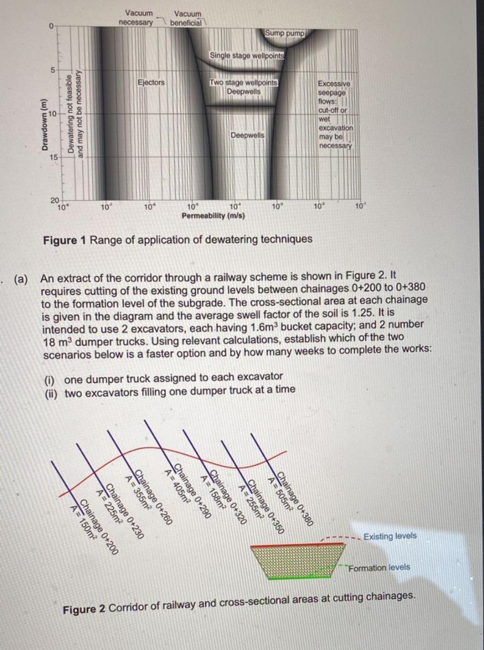
Vacuum Vacuum necessary beneficial Ejectors 15 20+ 10* 10 10* 10° 10° 10° 10 Permeability (m/s) 10' Figure 1 Range of application of dewatering techniques . (a) An extract of the corridor through a railway scheme is shown in Figure 2. It requires cutting of the existing ground levels between chainages 0+200 to 0+380 to the formation level of the subgrade. The cross-sectional area at each chainage is given in the diagram and the average swell factor of the soil is 1.25. It is intended to use 2 excavators, each having 1.6m³ bucket capacity; and 2 number 18 m³ dumper trucks. Using relevant calculations, establish which of the two scenarios below is a faster option and by how many weeks to complete the works: (i) one dumper truck assigned to each excavator (ii) two excavators filling one dumper truck at a time Existing levels 0 Drawdown (m) Dewatering not feasible and may not be necessary. Chainage 0+200 A = 150m² A = 225m² Chainage 0+230 A = 355m² Chainage 0+260 A = 405m² Chainage 0+290 A = 158m² Chainage 0+320 Single stage wellpoints Two stage wellpoints Deepwells Deepwells Sump pump A=255m² Chainage 0+350 A=505m² Chainage 0+380 Excessive seepage flows: cut-off or wet excavation may be necessary Formation levels Figure 2 Corridor of railway and cross-sectional areas at cutting chainages.
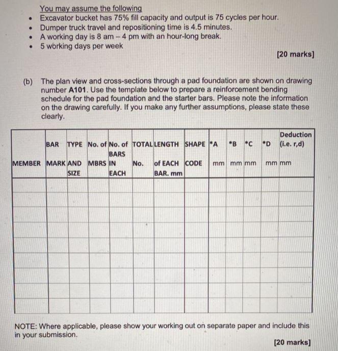
You may assume the following ● Excavator bucket has 75% fill capacity and output is 75 cycles per hour. • Dumper truck travel and repositioning time is 4.5 minutes. • A working day is 8 am - 4 pm with an hour-long break. ● 5 working days per week [20 marks] (b) The plan view and cross-sections through a pad foundation are shown on drawing number A101. Use the template below to prepare a reinforcement bending schedule for the pad foundation and the starter bars. Please note the information on the drawing carefully. If you make any further assumptions, please state these clearly. Deduction D (i.e. r,d) BAR TYPE No. of No. of TOTAL LENGTH SHAPE *A *B C BARS MEMBER MARK AND MBRS IN mm mm mm mm mm No. of EACH CODE BAR. mm SIZE EACH NOTE: Where applicable, please show your working out on separate paper and include this in your submission. [20 marks] E