Page 1 of 1
For the filter shown in Fig. 2, a) Derive an expression for the output voltages VHp. VBp and VLp versus Vin b) Find the
Posted: Thu May 26, 2022 10:51 am
by answerhappygod
- For The Filter Shown In Fig 2 A Derive An Expression For The Output Voltages Vhp Vbp And Vlp Versus Vin B Find The 1 (26.88 KiB) Viewed 24 times
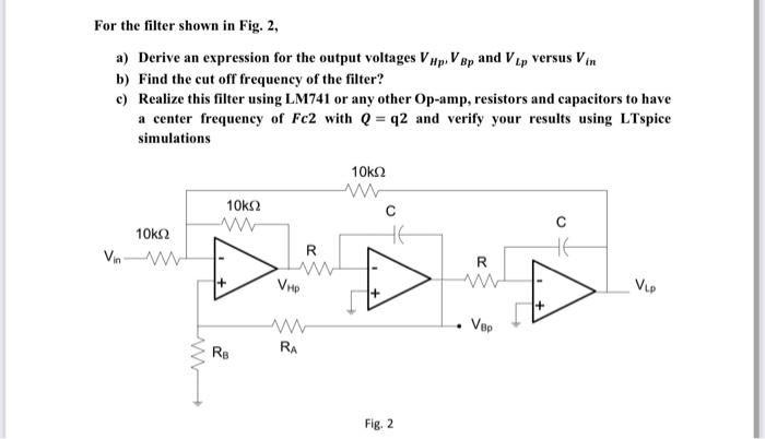
For the filter shown in Fig. 2, a) Derive an expression for the output voltages VHp. VBp and VLp versus Vin b) Find the cut off frequency of the filter? c) Realize this filter using LM741 or any other Op-amp, resistors and capacitors to have a center frequency of Fc2 with Q=q2 and verify your results using LTspice simulations 10ΚΩ www 10k2 C www 10ΚΩ Vin R R ADD www VH₂ 1+ Ver RA RB Fig. 2 2 VLP