Page 1 of 1
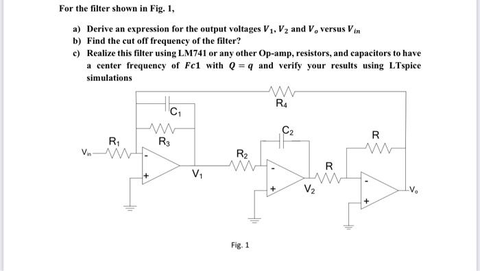
For the filter shown in Fig. 1, a) Derive an expression for the output voltages V₁, V₂ and V, versus Vin b) Find the cut
Posted: Thu May 26, 2022 10:51 am
by answerhappygod
- For The Filter Shown In Fig 1 A Derive An Expression For The Output Voltages V V And V Versus Vin B Find The Cut 1 (25.95 KiB) Viewed 24 times
For the filter shown in Fig. 1, a) Derive an expression for the output voltages V₁, V₂ and V, versus Vin b) Find the cut off frequency of the filter? c) Realize this filter using LM741 or any other Op-amp, resistors, and capacitors to have a center frequency of Fc1 with Q = q and verify your results using LTspice simulations ww R4 HC₁ www C₂ R www R₁ R3 Vin V₁ R₂ Fig. 1 1 + R www V₂