Page 1 of 1
Figure 11 is a Tow-Thomas low-pass filter topology. R₂ C₁ Rf W R₁ Vin Vout Figure 11 (a) What is the DC gain of the filt
Posted: Thu May 26, 2022 10:37 am
by answerhappygod
- Figure 11 Is A Tow Thomas Low Pass Filter Topology R C Rf W R Vin Vout Figure 11 A What Is The Dc Gain Of The Filt 1 (93.55 KiB) Viewed 22 times
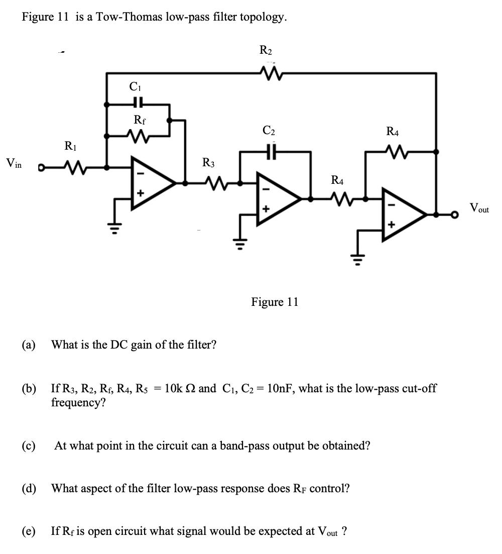
Figure 11 is a Tow-Thomas low-pass filter topology. R₂ C₁ Rf W R₁ Vin Vout Figure 11 (a) What is the DC gain of the filter? (b) If R3, R2, Rf, R4, R5 = 10k Q and C₁, C₂ = 10nF, what is the low-pass cut-off frequency? (c) At what point in the circuit can a band-pass output be obtained? (d) What aspect of the filter low-pass response does RF control? (e) If Rf is open circuit what signal would be expected at Vout ? R3 C₂ R4 R4