Page 1 of 1
= (d) The circuit shown in Figure 3 is designed to limit the peak-to-peak (p-p) voltage of Vout. If Vin is a 40 Vp-p sig
Posted: Thu May 26, 2022 10:33 am
by answerhappygod
- D The Circuit Shown In Figure 3 Is Designed To Limit The Peak To Peak P P Voltage Of Vout If Vin Is A 40 Vp P Sig 1 (79.98 KiB) Viewed 33 times
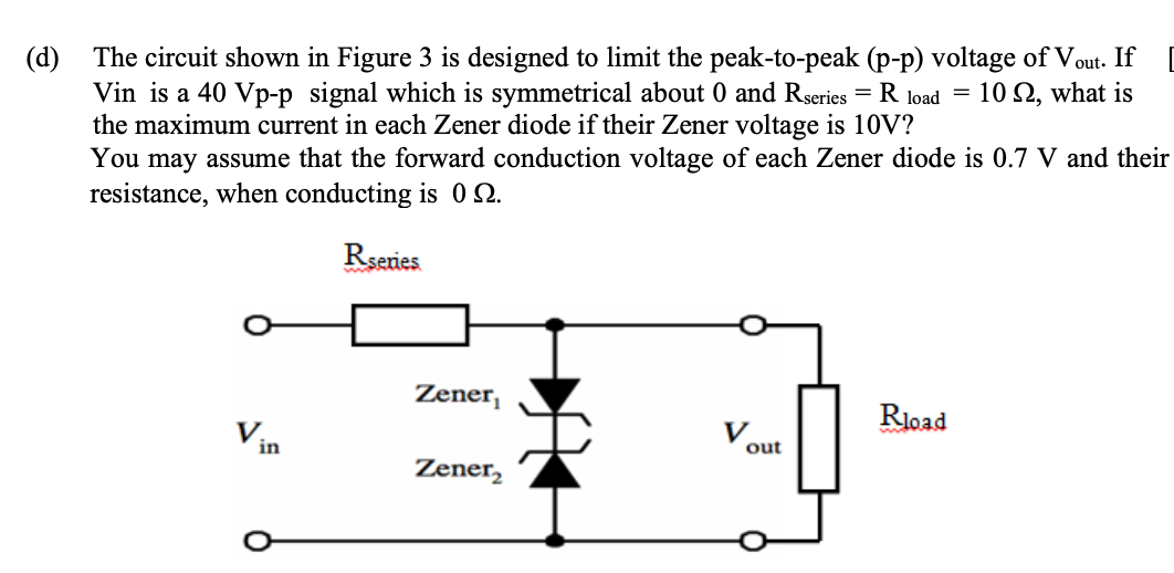
= (d) The circuit shown in Figure 3 is designed to limit the peak-to-peak (p-p) voltage of Vout. If Vin is a 40 Vp-p signal which is symmetrical about 0 and Rseries R load = 10 Q2, what is the maximum current in each Zener diode if their Zener voltage is 10V? You may assume that the forward conduction voltage of each Zener diode is 0.7 V and their resistance, when conducting is 02. Rseries Rload V Vin Zener, Zener₂ out