Page 1 of 1
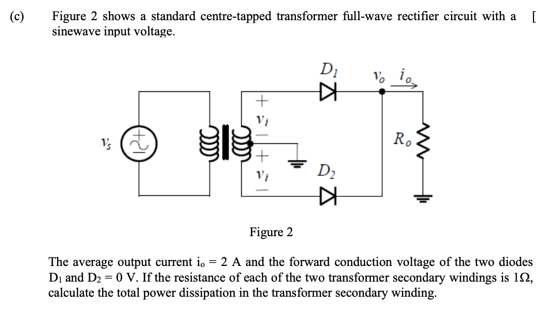
[ (c) Figure 2 shows a standard centre-tapped transformer full-wave rectifier circuit with a sinewave input voltage. D₁
Posted: Thu May 26, 2022 10:33 am
by answerhappygod
- C Figure 2 Shows A Standard Centre Tapped Transformer Full Wave Rectifier Circuit With A Sinewave Input Voltage D 1 (83.38 KiB) Viewed 37 times
[ (c) Figure 2 shows a standard centre-tapped transformer full-wave rectifier circuit with a sinewave input voltage. D₁ Ro 1/ Figure 2 The average output current io = 2 A and the forward conduction voltage of the two diodes D₁ and D₂ = 0 V. If the resistance of each of the two transformer secondary windings is 12, calculate the total power dissipation in the transformer secondary winding. (12+) ac )))))) += KH D₂ KH