Page 1 of 1
P2) Following is the feedback circuit compensated by a PI controller. C₁ R₂ C₂ R₁ HFWW + XI R₂ 0 dB 005 @0₁ 100 ₁-1 rad/
Posted: Thu May 26, 2022 10:08 am
by answerhappygod
- P2 Following Is The Feedback Circuit Compensated By A Pi Controller C R C R Hfww Xi R 0 Db 005 0 100 1 Rad 1 (47.67 KiB) Viewed 24 times
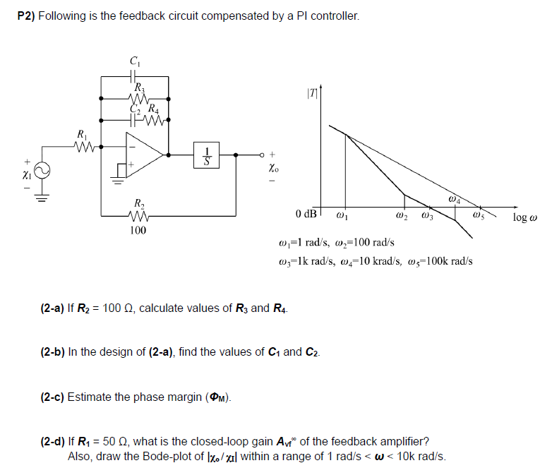
P2) Following is the feedback circuit compensated by a PI controller. C₁ R₂ C₂ R₁ HFWW + XI R₂ 0 dB 005 @0₁ 100 ₁-1 rad/s, w₂100 rad/s @3-1k rad/s, @4-10 krad/s, w5-100k rad/s (2-a) If R₂ = 100 , calculate values of R3 and R4. (2-b) In the design of (2-a), find the values of C₁ and C2. (2-c) Estimate the phase margin (PM). (2-d) If R₁ = 50 Q2, what is the closed-loop gain Avf of the feedback amplifier? Also, draw the Bode-plot of Ixo/xil within a range of 1 rad/s< w<10k rad/s. R₁ ww o + Xo (0)2 (4 log w