Page 1 of 1
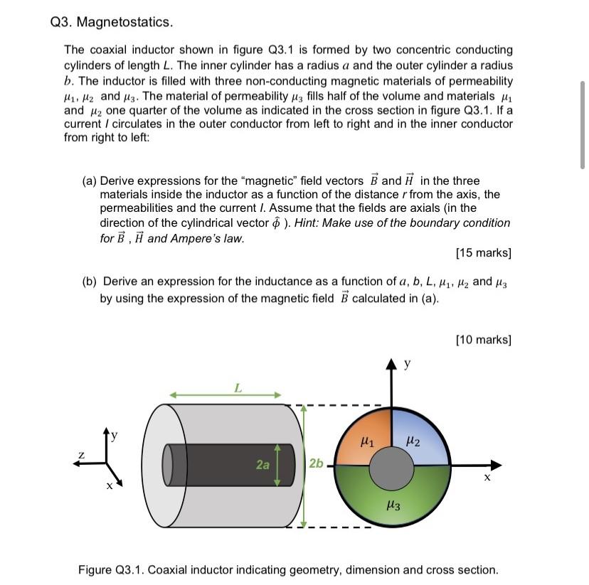
Q3. Magnetostatics. The coaxial inductor shown in figure Q3.1 is formed by two concentric conducting cylinders of length
Posted: Wed May 25, 2022 6:28 am
by answerhappygod
- Q3 Magnetostatics The Coaxial Inductor Shown In Figure Q3 1 Is Formed By Two Concentric Conducting Cylinders Of Length 1 (85.68 KiB) Viewed 28 times
Q3. Magnetostatics. The coaxial inductor shown in figure Q3.1 is formed by two concentric conducting cylinders of length L. The inner cylinder has a radius a and the outer cylinder a radius b. The inductor is filled with three non-conducting magnetic materials of permeability H1, H2 and 3. The material of permeability μ3 fills half of the volume and materials ₁ and ₂ one quarter of the volume as indicated in the cross section in figure Q3.1. If a current / circulates in the outer conductor from left to right and in the inner conductor from right to left: (a) Derive expressions for the "magnetic" field vectors B and in the three materials inside the inductor as a function of the distance r from the axis, the permeabilities and the current I. Assume that the fields are axials (in the direction of the cylindrical vector $). Hint: Make use of the boundary condition for B, H and Ampere's law. [15 marks] ₁, ₂ and μ3 (b) Derive an expression for the inductance as a function of a, b, L, by using the expression of the magnetic field B calculated in (a). [10 marks] y L Z 2a 2b X X μ3 Figure Q3.1. Coaxial inductor indicating geometry, dimension and cross section. μ1 1₂