Page 1 of 1
3) For the filter circuit of Fig.3 a) Find the transfer function(H(jo)) and cut-off frequency(fe) of the circuit with ge
Posted: Tue May 24, 2022 9:35 am
by answerhappygod
- 3 For The Filter Circuit Of Fig 3 A Find The Transfer Function H Jo And Cut Off Frequency Fe Of The Circuit With Ge 1 (152.98 KiB) Viewed 20 times
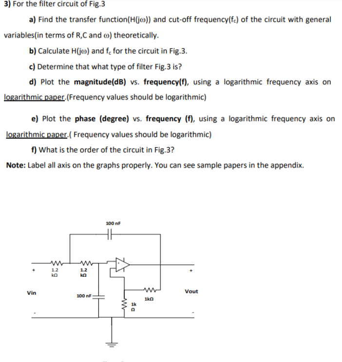
3) For the filter circuit of Fig.3 a) Find the transfer function(H(jo)) and cut-off frequency(fe) of the circuit with general variables (in terms of R,C and ) theoretically. b) Calculate H(jo) and f, for the circuit in Fig.3. c) Determine that what type of filter Fig.3 is? d) Plot the magnitude(dB) vs. frequency(f), using a logarithmic frequency axis on logarithmic paper. (Frequency values should be logarithmic) e) Plot the phase (degree) vs. frequency (f), using a logarithmic frequency axis on logarithmic paper.( Frequency values should be logarithmic) f) What is the order of the circuit in Fig.3? Note: Label all axis on the graphs properly. You can see sample papers in the appendix. 100 nF www 1.2 kQ Vout Vin 1.2 100 nF www a 1kQ